
Installation Guide


8. Place the new Primary Unit on the mounting bracket; insert the screw securing the
Primary Unit through the right side of the heat sink and into the bracket.
9. Screw the two conduit nuts in the Primary Unit securing the Connection Unit to the
Primary Unit.
10. Connect the DC, AC wires and the communication connectors to the Primary Unit.
11. For a 3 unit inverter reconnect the AC, DC and comm cables from the Connection
Unit to the right Secondary Unit.
12. Close the Primary Unit cover.
13. Perform the commissioning steps as described in
Activating, Commissioning and
Configuring the System Using the Inverter SetApp
on page 51.
14. In the monitoring platform, use the Replace button in the logical layout tab (in site
Admin).
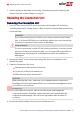
Replacing a Secondary Unit
1. Turn OFF the Inverter ON/OFF switch, and wait until the green LED is blinking ,
indicating that the DC voltage is safe (<50V), or wait five minutes before continuing
to the next step.
WARNING!
If you cannot see Primary Unit LEDs or you cannot connect to the Primary Unit,
or if the red LED light is on indicating a malfunction , wait five minutes for the
input capacitors of the inverter to discharge.
AVERTISSEMENT!
Si vous ne pouvez pas voir l'écran de l'onduleur ou si un dysfonctionnement est
indiqué sur l'écran LCD, attendez cinq minutes pour que les condensateurs
d'entrée de l'onduleur soient déchargés.
2. Disconnect the AC to the inverter by turning OFF the circuit breakers on the
distribution panel.
3. Disconnect all the connectors on the bottom of the Secondary Unit.
4. Remove the screw securing the Secondary Unit to the mounting bracket and remove
the Secondary Unit from the mounting bracket.
5. Place the new Secondary Unit on the mounting bracket.
6. Insert one of the supplied screws through the outer side of the heat sink and into
the bracket.
Appendix D: Replacing System Components 95
Three Phase Inverter with Synergy Technology Installation MAN-01-00401-1.5