
Installation Guide
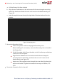
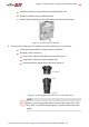


Figure 28: DC Spring-clamp terminals
5. Close the Connection Unit cover: Attach the switch cover and secure it by
tightening the six screws with a torque of 1.2 N*m / 0.9 ft.*lb.
6. Ensure proper conduit sealing; inspect the entire conduit run and use standard
conduit sealants to avoid water penetration.
Setting the Inverter to Support 208V 3-wire Grid
SolarEdge inverters that support the 208V 3-wire grid are equipped with two fuse
holders and a fuse in each unit. The position of the fuse configures the AC grid
connection: 4-wire or 3-wire grid connection. By default, the fuse is located in the 4-
wire fuse holder of the inverter, and in the 3-wire fuse holder there is a plastic dummy
fuse.
To set the inverter for 3-wire grid connection, you must move the fuse from the 4-wire
fuse holder, marked as Y GRID, to the 3-wire fuse holder, marked as ∆ GRID (see
Figure
29
).
To set the inverter for 208V 3-wire grid connection:
NOTE
Perform this procedure for all inverter units.
NOTE
Perform this procedure before connecting the inverterto the AC grid.
1.
Identify the fuse locations and the markings as described in
Figure 29
.
Figure 29: Fuse locations and markings
Chapter 4: Connecting the AC and Strings to the Connection Unit 49
Three Phase Inverter with Synergy Technology Installation MAN-01-00401-1.5