
Installation Manual

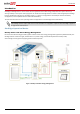

Backup Power with Smart Energy Management - System Configurations
7
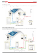
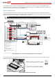
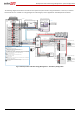
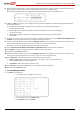
The following diagram illustrates the connection of the system components when using two batteries. In this case, an external
fused combiner box is needed. For enlarged segments of this diagram, refer to Appendix D – Detailed System Connection.
Figure 6: Backup Power with Smart Energy Management - Two-Battery Configuration
20A
CB
20A
CB
20A
CB
20A
CB
Backed-up Loads Distribution Panel
BU_L1
BU_L2
25A
CB
25A
CB
BU_N
Backup Neutral bus-bar
3
Meter AC [L1, L2, N], 12 -16 AWG
3
Inverter AC Backup [L1, L2, N], 6 AWG (4-20 AWG)
Backup
Panel Main
Breaker
Backed-up Loads
Breakers
RS485
SolarEdge
Meter
A -
B+
G
N
ØL1
ØL2
ØL3
L1 CT
L2 CT
L3 CT
To the backed-up loads
Notes 4
3/4" Conduit
L1 L2
Main
Distribution
Panel
CT
CT
RS485
CB
CB
15A CB
15A CB
CB
40A CB
CB
40A CB
Neutral
bus-bar
L1_Grid
N_Grid
L2_Grid
Connection to utility meter
L1
N
L2
3
3
1/2" Conduit
Main Breaker
3/4" Conduit
1" Conduit
RS485 [A,B,G], 24 AWG (16-24 AWG),
Shielded twisted pair, 600V insulated
Inverter AC Grid [L1, L2, N], 6 AWG (4-20 AWG)
PV DC+, 10 AWG (4-20 AWG), 600V insulated
PV DC- , 10 AWG (4-20 AWG), 600V insulated
Batt. HV DC+, 10AWG (10-12 AWG), 600V ins.
Batt. HV DC-, 10AWG (10-12 AWG), 600V ins.
+
-
V+
V-
2
PWR
V+
G
5
RTN
En
A+
B-
EN
P
N
Thermal [V+, V-], 16 AWG (12-16 AWG),
Shielded pair, 600V insulated
Control [V+, G, En, A+, B-], 24AWG (16-24 AWG),
Shielded pair, 600V insulated
+
-
PWR
RTN
EN
P
N
12A/600V fuses
Fused combiner box
1
st
port
2
nd
port
1
st
port
Thermal
Battery #1
RS485
Not
Terminated
Thermal
Battery HV DC+, 10AWG (10-12 AWG), 600V insulated
Battery HV DC- , 10AWG (10-12 AWG), 600V insulated
Battery HV DC+
Battery HV DC-
PWR
EN
P
N
RTN
Battery #2
RS485
Terminated and
biased
RTN
EN
P
N
2
nd
port
Battery #1 switches settings:
Battery #2 switches settings:
3/4" Conduit
StorEdge
Inverter
Auto-
transformer
3/4" Conduit
L1_A.T.
N_A.T.
L2_A.T.
T1
T2
Auto-transformer AC [L1,
L2, N], 8 AWG (6-20 AWG)
3
2
Temp. sense [T1, T2], 24 AWG
(16-24 AWG), 600V insulated
L1_A.T.
N_A.T.
L2_A.T.
T1
T2
L1_BU
L2_BU
N_BU
CB
CB
CBCB
CBCB
CB
CB
CB
CB
CB
CB
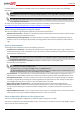
Notes
Note 1: StorEdge Inverter:
SE7600A-USS0 supports double capacity
SE7600A-USS2 supports double power and double capacity
- Replace the internal 12A fuses with 25A fuses for two batteries
Recommended Fuses in StorEdge Inverter:
12A 600VDC Quick-Acting, 10 x 38 mm Solar Midget Fuses (Example: Littelfuse P/N 0SPF012)
25A 600VDC Quick-Acting, 10 x 38 mm Solar Midget Fuses (Example: Littelfuse P/N 0SPF025)
Note 2: External fused combiner box is needed to support two batteries.
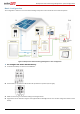
Note 3: Auto-transformer connection:
6ft max
Vertical mounting only (conduit connection from the bottom)
Use 10 AWG wire for grounding
Note 4: Battery connection:
35ft max
Distance larger than 5ft requires installation of external DC safety switch on the battery side
Control [B-,A+] must be twisted pair
Note 5: Use a twin-wire ferrules to daisy chain the thermal wiring
Note 6: Install type B 2- pole 25A main circuit breaker to ensure the 25A phase limit imbalance is
maintained at all times.
Note 1
Note 3
Note 4
Note 2
Note 5
RS485-1 Terminations
Move up the left switch
BAT
IN
Fuses
12A/25A
8 ft twisted pair supplied with the CT
Meter is required only for Smart Energy Managment
Type B for main circuit breakers