
Installation Manual


Appendix D – Detailed System Connection
37
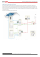
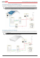
Figure 30: Backup Power with Smart Energy Management - Basic Configuration
L1 L2
Main
Distribution
Panel
CT
CT
CB
CB
15A CB
40A CB
CB
40A CB
Neutral
bus-bar
L1_Grid
N_Grid
L2_Grid
20A
CB
20A
CB
20A
CB
20A
CB
Backed-up Loads Distribution Panel
BU_L1
BU_L2
Connection to utility meter
25A
CB
25A
CB
BU_N
L1
N
L2
1" Conduit
Backup Neutral bus-bar
3
Meter AC [L1, L2, N], 12-16 AWG
8 ft twisted pair supplied with the CT
Meter is required only for Smart Energy Managment
RS485 [A,B,G], 24 AWG (16-24 AWG),
Shielded twisted pair, 600V insulated
3
Inverter AC Grid [L1, L2, N], 6 AWG (4-20 AWG)
3
3
Inverter AC Backup [L1, L2, N], 6 AWG (4-20 AWG)
Backup
Panel Main
Breaker
Backed-up Loads
Breakers
Type B for main circuit breakers
Battery HV DC+, 10 AWG (8-12 AWG), 600V insulated
Battery HV DC- , 10 AWG (8-12 AWG), 600V insulated
+
-
V+
V-
2
Thermal [V+, V-], 16AWG (12-16 AWG),
Shielded pair, 600V insulated
PWRV+
G
5
Control [V+, G, En, A+, B-], 24AWG (16-24 AWG),
Shielded twisted pairs, 600V insulated
RTN
En
A+
B-
EN
P
N
Auto-
transformer
3/4" Conduit
3/4" Conduit
L1_A.T.
N_A.T.
L2_A.T.
T1
T2
L1_A.T.
N_A.T.
L2_A.T.
T1
T2
Auto-transformer AC [L1, L2, N], 8 AWG (6-20 AWG)
3
2
Temp. sense [T1, T2], 24AWG (16-24 AWG),
600V insulated
RS485
SolarEdge
Meter
A -
B+
G
N
ØL1
ØL2
ØL3
L1 CT
L2 CT
L3 CT
Main Breaker
To the backed-up loads
3/4" Conduit
PV DC+, 10 AWG (4-20 AWG), 600V insulated
PV DC- , 10 AWG (4-20 AWG), 600V insulated
2
2
StorEdge
Inverter
BAT
IN
Fuses
12A
CB
CB
CBCB
CBCB
CB
CB
CB
CB
CB
CB
15A CB
CB
Notes
Note 1: Recommended Fuses in StorEdge Inverter:
12A 600VDC Quick-Acting, 10 x 38 mm Solar Midget Fuses
(Example: Littelfuse P/N 0SPF012)
Note 2: Auto-transformer connection:
6ft max
Vertical mounting only (conduit connection from the bottom)
Use 10 AWG wire for grounding
Note 3: Battery connection:
35ft max
Distance larger than 5ft requires installation of external DC
safety switch on the battery side
Control [B-,A+] must be twisted pair
Note 4: Install type B 2-pole 25A main circuit breaker to ensure the
25A phase limit imbalance is maintained at all times.
Notes 1
Notes 2
Notes 3
L1_BU
L2_BU
N_BU
RS485-1 Terminations
Move up the left switch
Notes 4
1/2" Conduit
3/4" Conduit
Battery
Battery switches settings:
RS485