
Installation Manual

Smart Energy Management Only - System Configurations
28
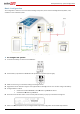
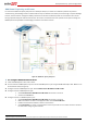
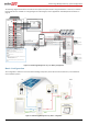
The following diagram illustrates the connection of the system components when using two batteries. In this case, an external
fused combiner box is needed. For enlarged segments of this diagram, refer to Appendix D – Detailed System Connection on
page 53.
Figure 22: Smart Energy Management only - Two Battery Configuration
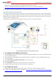
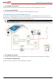
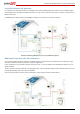
Basic Configuration
This configuration is based on one of each of the StorEdge components, other than the auto-transformer, and is suitable for
most residential systems.
Figure 23: Smart Energy Management only - Basic configuration
3
Meter AC [L1, L2, N], 12 -16 AWG
8 ft twisted pair supplied with the CT
RS485
SolarEdge
Meter
A -
B+
G
N
ØL1
ØL2
ØL3
L1 CT
L2 CT
L3 CT
L1 L2
Main
Distribution
Panel
CT
CT
RS485
CB
CB
15A CB
15A CB
CB
40A CB
CB
40A CB
Neutral
bus-bar
L1_Grid
N_Grid
L2_Grid
Connection to utility meter
L1
N
L2
3
3
1/2" Conduit
Main Breaker
3/4" Conduit
1" Conduit
RS485 [A,B,G], 24 AWG (16-24 AWG),
Shielded twisted pair, 600V insulated
Inverter AC Grid [L1, L2, N], 6 AWG (4-20 AWG)
PV DC+, 10 AWG (4-20 AWG), 600V insulated
PV DC- , 10 AWG (4-20 AWG), 600V insulated
Batt. HV DC+, 10AWG (10-12 AWG), 600V ins.
Batt. HV DC-, 10AWG (10-12 AWG), 600V ins.
+
-
V+
V-
2
PWR
V+
G
5
RTN
En
A+
B-
EN
P
N
Thermal [V+, V-], 16 AWG (12-16 AWG),
Shielded pair, 600V insulated
Control [V+, G, En, A+, B-], 24AWG (16-24 AWG),
Shielded pair, 600V insulated
+
-
PWR
RTN
EN
P
N
12A/600V fuses
Fused combiner box
1
st
port
2
nd
port
1
st
port
Thermal
Battery #1
RS485
Not
Terminated
Thermal
Battery HV DC+, 10AWG (10-12 AWG), 600V insulated
Battery HV DC- , 10AWG (10-12 AWG), 600V insulated
Battery HV DC+
Battery HV DC-
PWR
EN
P
N
RTN
Battery #2
RS485
Terminated and
biased
RTN
EN
P
N
2
nd
port
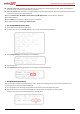
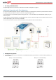
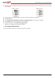
Battery #1 switches settings:
Battery #2 switches settings:
3/4" Conduit
StorEdge
Inverter*
BAT
IN
Fuses
12A
CB
CB
CBCB
CBCB
CB
CB
CB
CB
CB
CB
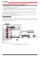
Notes
Note 1: Recommended Fuses in StorEdge Inverter:
12A 600VDC Quick-Acting, 10 x 38 mm Solar Midget Fuses
(Example: littelfuse P/N 0SPF012)
Note 2: External fused combiner box is needed to support two
batteries
Note 3: Battery connection:
35ft max
Distance larger than 5ft requires installation of external DC safety
switch on the battery side
Control [B-,A+] must be twisted pair
Note 4: Use a twin-wire ferrules to daisy chain the thermal wiring
Note 1
Note 3
Note 2
Note 4
RS485-1 Terminations
Move up the left switch