
Installation Manual

Smart Energy Management Only - System Configurations
27
Smart Energy Management Only - System Configurations
In this mode stored energy is used for Smart Energy Management applications only:
Maximize self-consumption – the battery is automatically charged and discharged to meet consumption needs and reduce
the amount of electricity purchased from the grid.
Charge/discharge profile programming – the system operates according to a configurable charge/discharge profile, for
example for time of use arbitrage (charge the battery from PV/grid when tariffs are low and discharge it when tariffs are
high).
A Smart Energy Management only system can be upgraded to support backup power by installing an auto-transformer and
connecting backed-up loads through a separate panel, and reconfiguring the system as described in Backup Power with Smart
Energy Management - System Configurations on page 5.
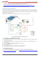
Configuration is done as described in the Backup Power with Smart Energy Management - System Configurations chapter,
without setting up backup power. System diagrams are shown below.
System Connection
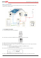
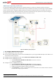
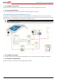
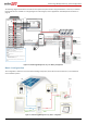
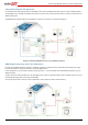
The following diagram illustrates the connection of the system components when using the basic configuration for Smart Energy
Management only: one StorEdge inverter, one meter and one battery. For enlarged segments of this diagram refer to Appendix
D – Detailed System Connection on page 53.
.
Figure 21: Smart Energy Management only - Basic Configuration
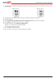
Battery
L1 L2
Main
Distribution
Panel
CT
CT
CB
CB
15A CB
40A CB
CB
40A CB
Neutral
bus-bar
L1_Grid
N_Grid
L2_Grid
Connection to utility meter
L1
N
L2
1" Conduit
3
Meter AC [L1, L2, N], 12 -16 AWG
8 ft twisted pair supplied with the CT
RS485 [A,B,G], 24 AWG (16-24 AWG),
Shielded twisted pair, 600V insulated
3
Inverter AC Grid [L1, L2, N], 6 AWG (4-20 AWG)
3
1" Conduit
Battery HV DC+, 10 AWG (8-12 AWG), 600V insulated
Battery HV DC- , 10 AWG (8-12 AWG), 600V insulated
+
-
V+
V-
2
Thermal [V+, V-], 16AWG (12-16 AWG),
Shielded pair, 600V insulated
PWRV+
G
5
Control [V+, G, En, A+, B-], 24AWG (16-24 AWG),
Shielded twisted pairs, 600V insulated
RTN
En
A+
B-
EN
P
N
3/4" Conduit
RS485
SolarEdge
Meter
A -
B+
G
N
ØL1
ØL2
ØL3
L1 CT
L2 CT
L3 CT
Main Breaker
3/4" Conduit
PV DC+, 10 AWG (4-20 AWG), 600V insulated
PV DC- , 10 AWG (4-20 AWG), 600V insulated
2
2
StorEdge
Inverter
BAT
IN
Fuses
12A
CB
CB
CBCB
CBCB
CB
CB
CB
CB
CB
CB
15A CB
CB
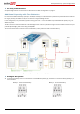
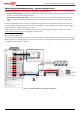
Notes
Note 1: Recommended Fuses in StorEdge Inverter:
12A 600VDC Quick-Acting, 10 x 38 mm Solar Midget Fuses
(Example: littelfuse P/N 0SPF012)
Note 2: Battery connection:
35ft max
Distance larger than 5ft requires installation of external DC
safety switch on the battery side
Control [B-,A+] must be twisted pair
Notes 1
Notes 2
RS485
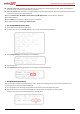
RS485-1 Terminations
Move up the left switch
Battery switches settings: