
Installation Manual
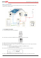

Backup Power Only - System Configurations
22
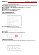
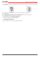
S_OK: Indicates that the connection to the SolarEdge monitoring portal is successful.
If S_OK is not displayed and/or errors are displayed on the LCD, refer to Errors and Troubleshooting in
http://www.solaredge.com/files/pdfs/products/inverters/se-single-and-three-phase-inverter-user-manual-na.pdf.
3 For additional verification, refer to Appendix C – Verifying StorEdge Functionality on page 35.
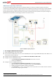
Large Residential PV Systems
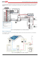
For residential sites with large PV systems, a StorEdge inverter and a SolarEdge single phase inverter may be installed together.
The StorEdge inverter manages the battery and functions as a PV inverter, and the second inverter is used for production of the
additional PV power. During power outages, the StorEdge inverter provides power to backed-up loads, and the second inverter
remains shut down until the grid is back.
An RS485 Expansion Kit (available from SolarEdge) is installed in the inverter connected to the battery.
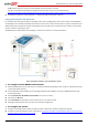
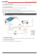
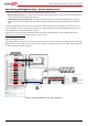
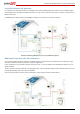
Figure 17: Backup Power Only - Large residential PV systems
► To configure inverter RS485 communication:
1 Install the RS485 Expansion Kit in the inverter connected to the battery (SolarEdge inverter in Figure 17: Backup Power Only
- Large residential PV systems).
2 Connect SolarEdge inverter RS485-1 port to SolarEdge standard inverter RS485-1 port using an RS485 twisted pair cable.
Terminate both sides.
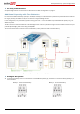
3 Select Communication RS485-E Conf Enable. Press Enter to continue.
4 Select Protocol Master.
5 Select Slave Detect. Verify that the inverter reports the correct number of slaves.
6 SolarEdge standard Inverter does not require communication configuration.
► To configure the system:
1 Configure the StorEdge inverter battery and backup power as described in the Basic Configuration page 20.
2 Configure the second SolarEdge inverter as described in http://www.solaredge.com/files/pdfs/products/inverters/se-single-
and-three-phase-inverter-user-manual-na.pdf.