
Installation Manual
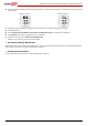


Backup Power Only - System Configurations
18
Backup Power Only - System Configurations
In this mode, stored energy is used for backup power only. In case of a power outage, the inverter automatically switches to
backup mode, disconnecting from the grid and supplying power to backed-up loads.
A backup power only system can be upgraded to support Smart Energy Management applications by installing a SolarEdge
Electricity Meter and reconfiguring the system as described in Backup Power with Smart Energy Management - System
Configurations on page 5.
The configurations described in this section are the same as the configurations described above; system diagrams and
configuration details are for backup power only (for full descriptions of each configuration refer to Table 1: Backup Power with
Smart Energy Management Configurations page 5):
Basic Configuration
Large Residential PV Systems
Additional Capacity with Two Batteries
Additional Capacity and Power
AC Coupling using a non-SolarEdge Inverter
System Connection
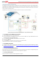
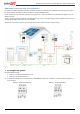
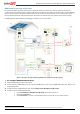
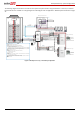
The following diagram illustrates the connection of the system components when using the basic configuration for backup
power only: one StorEdge inverter, one auto-transformer and one battery. For enlarged segments of this diagram refer to
Appendix D – Detailed System Connection on page 45.
NOTE
Install the GFDI (Ground-Fault Detector Interrupter) in accordance with applicable local standards and directives.
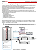
Figure 14: Backup Power only - Basic Configuration
Battery
L1 L2
CB
Main
Distribution
Panel
CB
CB
40A CB
CB
40A CB
Neutral
bus-bar
L1_Grid
N_Grid
L2_Grid
20A
CB
20A
CB
20A
CB
20A
CB
Backed-up Loads Distribution Panel
BU_L1
BU_L2
Connection to utility meter
25A
CB
25A
CB
BU_N
L1
N
L2
1" Conduit
Backup Neutral bus-bar
3
Inverter AC Grid [L1, L2, N], 6 AWG (4-20 AWG)
3
Inverter AC Backup [L1, L2, N],
6 AWG (4-20 AWG)
Backup
Panel Main
Breaker
Backed-up Loads
Breakers
Battery HV DC+, 10 AWG (8-12 AWG), 600V insulated
Battery HV DC- , 10 AWG (8-12 AWG), 600V insulated
+
-
V+
V-
2
Thermal [V+, V-], 16AWG (12-16 AWG),
Shielded pair, 600V insulated
PWRV+
G
5
Control [V+, G, En, A+, B-], 24AWG (16-24 AWG),
Shielded twisted pairs, 600V insulated
RTN
En
A+
B-
EN
P
N
Auto-
transformer
3/4" Conduit
3/4" Conduit
L1_A.T.
N_A.T.
L2_A.T.
T1
T2
L1_A.T.
N_A.T.
L2_A.T.
T1
T2
Auto-transformer AC [L1, L2, N], 8 AWG (6-20 AWG)
3
2
Temp. sense [T1, T2], 24AWG (16-24 AWG),
600V insulated
Main Breaker
To the backed-up loads
PV DC+, 10 AWG (4-20 AWG), 600V insulated
PV DC- , 10 AWG (4-20 AWG), 600V insulated
2
2
StorEdge
Inverter
BAT
IN
Fuses
12A
CB
CB
CBCB
CBCB
CB
CB
CB
CB
CB
CB
CB
CB
Notes
Note 1: Recommended Fuses in StorEdge Inverter:
12A 600VDC Quick-Acting, 10 x 38 mm Solar Midget Fuses
(Example: Littelfuse P/N 0SPF012)
Note 2: Auto-transformer connection:
6ft max
Vertical mounting only (conduit connection from the bottom)
Use 10 AWG wire for grounding
Note 3: Battery connection:
35ft max
Distance larger than 5ft requires installation of external DC
safety switch on the battery side
Control [B-,A+] must be twisted pair
Note 4: Install type B 2- pole 25A main circuit breaker to ensure
the 25A phase limit imbalance is maintained at all times.
Notes 1
Notes 2
Notes 3
L1_BU
L2_BU
N_BU
RS485-1 Terminations
Move up the left switch
Note 4
3/4" Conduit
3/4" Conduit
Battery switches settings:
Type B for main circuit breakers