
Installation Guide


Table Of Contents
- Disclaimers
- Revision History
- HANDLING AND SAFETY INSTRUCTIONS
- IMPORTANT INVERTER SAFETY INSTRUCTIONS
- Chapter 1: Overview
- Chapter 2: Installing the Power Optimizers
- Chapter 3: Installing the Inverter
- Chapter 4: Auto-transformer and Backed-up Loads Panel Installation (for Backup)
- Chapter 5: Meter Installation
- Chapter 6: Commissioning the Installation
- Chapter 7: StorEdge Inverter Connections
- Chapter 8: User Interface
- Chapter 9: Setting Up Communication to the Monitoring Platform
- Chapter 10: System Configuration
- Appendix A: Troubleshooting
- Appendix B: Opening Conduit Drill Guides
- Appendix C: Replacing and Adding System Components
- Appendix D: External Rapid Shutdown
- Appendix E: Mechanical Specifications
- Appendix F: Powering the LG Chem Battery Off and On
- StorEdge Single Phase Inverter with Connection Unit for High Power Technical ...
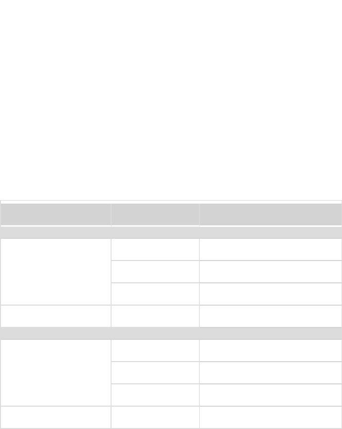
Figure 31: Connection to grid, backed-up loads
Prepare cables and connect as described in the following table:
Recommended cable type
(min-max AWG)
StorEdge Connection
Unit connection
External connection
Grid
6 AWG (4-20 AWG)
3-pin terminal block:
Grid L1
Main distribution panel: L1
3-pin terminal block:
Grid L2
Main distribution panel: L2
3-pin terminal block:
Grid N
Main distribution panel: N
Min. 10 AWG grounding
wire
to ground
Backed-up loads panel
6 AWG (4-20 AWG)
3-pin terminal block:
L1
Backed-up loads panel: L1
3-pin terminal block:
L2
Backed-up loads panel: L2
3-pin terminal block:
N
Backed-up loads panel: N
Min. 10 AWG grounding
wire
to ground
StorEdge Solution with Backup MAN-01-00262-1.5
70 Connecting to AC