
Installation Guide


Table Of Contents
- Disclaimers
- Revision History
- HANDLING AND SAFETY INSTRUCTIONS
- IMPORTANT INVERTER SAFETY INSTRUCTIONS
- Chapter 1: Overview
- Chapter 2: Installing the Power Optimizers
- Chapter 3: Installing the Inverter
- Chapter 4: Auto-transformer and Backed-up Loads Panel Installation (for Backup)
- Chapter 5: Meter Installation
- Chapter 6: Commissioning the Installation
- Chapter 7: StorEdge Inverter Connections
- Chapter 8: User Interface
- Chapter 9: Setting Up Communication to the Monitoring Platform
- Chapter 10: System Configuration
- Appendix A: Troubleshooting
- Appendix B: Opening Conduit Drill Guides
- Appendix C: Replacing and Adding System Components
- Appendix D: External Rapid Shutdown
- Appendix E: Mechanical Specifications
- Appendix F: Powering the LG Chem Battery Off and On
- StorEdge Single Phase Inverter with Connection Unit for High Power Technical ...
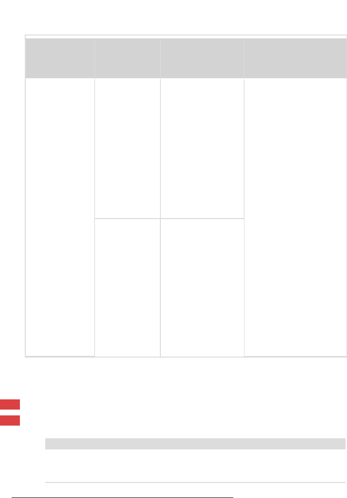
Recommended
cable type
(min-max AWG)
StorEdge
Connection Unit
connection
Auto-transformer
connection
Connection method
Temperature
sensor terminal
24 AWG (16-24
AWG), 300 Vrms
insulated
External Devices
7-pin terminal
block: T1
Temperature sensor
terminal: T1
(1)
StorEdge Connection
Unit: Press the protrusion
at the top of the terminal
block to open the
connection hole, insert
the wire and release to
spring back and clamp
the wire.
Auto-transformer:
1. Insert a flat blade
screwdriver into the
square opening at the
top of the terminal
block and press to
open clamp
mechanism.
2. Insert the wire into the
round opening and
release the screwdriver
to spring back and
clamp the wire.
External Devices
7-pin terminal
block: T2
Temperature sensor
terminal: T2
Connecting to the Grid and to Backed-up Loads
This section describes:
Connection to the ACGrid.
Connection between the inverter to the backed-up loads panel.
NOTE
If there are multiple inverters in the installation, each inverter should be
connected to a separate backed-up loads panel. Do not share backup output
between inverters.
(1)
T1 and T2 are interchangable
Chapter 7: StorEdge Inverter Connections 69
StorEdge Solution with Backup MAN-01-00262-1.5