
Installation Guide


Table Of Contents
- Disclaimers
- Revision History
- HANDLING AND SAFETY INSTRUCTIONS
- IMPORTANT INVERTER SAFETY INSTRUCTIONS
- Chapter 1: Overview
- Chapter 2: Installing the Power Optimizers
- Chapter 3: Installing the Inverter
- Chapter 4: Auto-transformer and Backed-up Loads Panel Installation (for Backup)
- Chapter 5: Meter Installation
- Chapter 6: Commissioning the Installation
- Chapter 7: StorEdge Inverter Connections
- Chapter 8: User Interface
- Chapter 9: Setting Up Communication to the Monitoring Platform
- Chapter 10: System Configuration
- Appendix A: Troubleshooting
- Appendix B: Opening Conduit Drill Guides
- Appendix C: Replacing and Adding System Components
- Appendix D: External Rapid Shutdown
- Appendix E: Mechanical Specifications
- Appendix F: Powering the LG Chem Battery Off and On
- StorEdge Single Phase Inverter with Connection Unit for High Power Technical ...
To connect the Ethernet cable:
1. Remove the inverter cover as described in
Removing the Inverter Cover
on page 45.
2.
Open the communication gland #1.
CAUTION!
The gland includes a rubber waterproof fitting, which should be used to
ensure proper sealing.
ATTENTION!
Le cote interne du gland contient une rondelle qui doit être utilisée pour
une bonne étancheïté.
3. Remove the plastic seal from one of the large opening .
4. Remove the rubber fitting from the gland and insert the CAT5/6 cable through the
gland and through the gland opening in the inverter
5.
Push the cable into the cut opening of the rubber fitting.
Figure 36: Rubber fitting
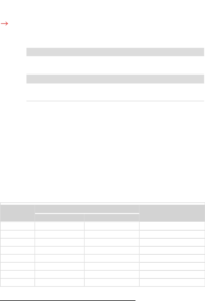
CAT5/6 standard cables have eight wires (four twisted pairs), as shown in the diagram
below. Wire colors may differ from one cable to another. You can use either wiring
standard, as long as both sides of the cable have the same pin-out and color-coding.
RJ45 Pin #
Wire Color
(1)
10Base-T Signal
100Base-TX Signal
T568B T568A
1 White/Orange White/Green Transmit+
2 Orange Green Transmit-
3 White/Green White/Orange Receive+
4 Blue Blue Reserved
5 White/Blue White/Blue Reserved
6 Green Orange Received-
7 White/Brown White/Brown Reserved
8 Brown Brown Reserved
(1)
The inverter connection does not support RX/TX polarity change. Supporting crossover Ethernet cables depends on
the switch capabilities.
StorEdge Solution with Backup MAN-01-00262-1.5
102 Creating an Ethernet (LAN) Connection