
Install Manual

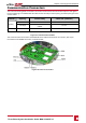
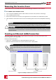
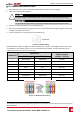
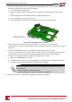

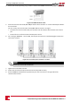
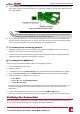
Table Of Contents
- Disclaimers
- Support and Contact Information
- Revision History
- HANDLING AND SAFETY INSTRUCTIONS
- IMPORTANT SAFETY INSTRUCTIONS
- Chapter 1: Introducing the SolarEdge Power Harvesting System
- Chapter 2: Installing the Power Optimisers
- Chapter 3: Installing the Inverter
- Chapter 4: Connecting the AC and the Strings to the Safety Switch
- Chapter 5: Activating, Commissioning and Configuring the System Using the Inverter SetApp
- Chapter 6: Setting Up Communication
- Appendix A: Errors and Troubleshooting
- Appendix B: Mechanical Specifications
- Appendix C: External Fan Maintenance and Replacement
- Appendix D: Replacing and Adding System Components
- Technical Specifications - Three Phase Inverters (North America)

4.
LoosenthescrewsofpinsA(+),B(-),andGontheleftoftheRS485terminalblock(RS485-1orRS485-2).
Figure 34: RS485 terminal block
5.
InsertthewireendsintotheG, AandBpinsshownabove.UseFour-orsix-wiretwistedpaircablefor
thisconnection.
YoucanuseanycolorwireforeachoftheA,BandGconnections,aslongas:
l ThesamecolorwireisusedforallApinsthesamecolorforallBpinsandthesamecolorforallG
pins
l ThewireforGisnotfromthesametwistedpairasAorB.
6.
ForcreatinganRS485bus-connectallB,AandGpinsinallinverters.Thefollowingfigureshowsthis
connectionschema:
Figure 35: Connecting the inverters in a chain
NOTE
Do not cross-connect B, A and G wires.
7. Tightentheterminalblockscrews.
8. Checkthatthewiresarefullyinsertedandcannotbepulledouteasily.
9.
PushtheRS485terminalblockfirmlyallthewayintotheconnectorontherightsideofthe
communicationboard.
-Three Phase System Installation Guide MAN-01-00527-1.1
58
Creating an RS485 Bus Connection