
Install Manual
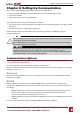
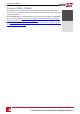
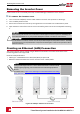
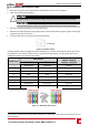
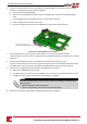

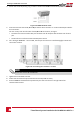
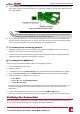
Table Of Contents
- Disclaimers
- Support and Contact Information
- Revision History
- HANDLING AND SAFETY INSTRUCTIONS
- IMPORTANT SAFETY INSTRUCTIONS
- Chapter 1: Introducing the SolarEdge Power Harvesting System
- Chapter 2: Installing the Power Optimisers
- Chapter 3: Installing the Inverter
- Chapter 4: Connecting the AC and the Strings to the Safety Switch
- Chapter 5: Activating, Commissioning and Configuring the System Using the Inverter SetApp
- Chapter 6: Setting Up Communication
- Appendix A: Errors and Troubleshooting
- Appendix B: Mechanical Specifications
- Appendix C: External Fan Maintenance and Replacement
- Appendix D: Replacing and Adding System Components
- Technical Specifications - Three Phase Inverters (North America)

Creating an RS485 Bus Connection
TheRS485optionenablescreatingabusofconnectedinverters,consistingofupto31slaveinvertersand
1masterinverter.Usingthisoption,invertersareconnectedtoeachotherinabus(chain),viatheir
RS485connectors.Thefirstandlastinvertersinthechainmustbeterminatedasdescribedonpage59.
RS485wiringspecifications:
l Cabletype:Min.3-wireshieldedtwistedpair(ashieldedEthernetcable(Cat5/5ESTP)maybeused)
l Wirecross-sectionarea:0.2-1mm²/24-18AWG(aCAT5cablemaybeused)
l Maximumnodes:32
l Maximumdistancebetweenfirstandlastdevices:1km/3300ft.
NOTE
If using a cable longer than 10 m/33 ft in areas where there is a risk of induced
voltage surges by lightning, it is recommend to use external surge protection
devices. For details refer to:
https://www.solaredge.com/sites/default/files/overvoltage_surge_protection_
na.pdf.
If grounded metal conduit are used for routing the communication wires, a lightning
protection device is not required.
If not using surge protection, connect the grounding wire to the first inverter in the RS485 chain;
make sure the grounding wire is not in contact with other wires. Connect the grounding wire to the
grounding bus-bar in the Safety Switch.
ThefollowingsectionsdescribehowtophysicallyconnecttheRS485busandhowtoconfigurethebus.
To connect the RS485 communication bus:
1. RemovetheinvertercoverasdescribedinRemovingtheInverterCoveronpage54.
2. Removethesealfromoneoftheopeningsincommunicationgland#2andinsertthewirethrough
theopening.
3.
Pulloutthe6-pinRS485terminalblockconnector,asshownbelow:
Figure 33: The RS485 terminal block
Chapter 6: Setting Up Communication
-Three Phase System Installation Guide MAN-01-00527-1.1
57