
Install Manual
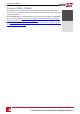
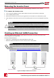
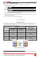
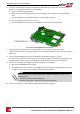

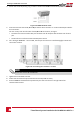
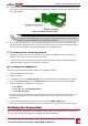
Table Of Contents
- Disclaimers
- Support and Contact Information
- Revision History
- HANDLING AND SAFETY INSTRUCTIONS
- IMPORTANT SAFETY INSTRUCTIONS
- Chapter 1: Introducing the SolarEdge Power Harvesting System
- Chapter 2: Installing the Power Optimisers
- Chapter 3: Installing the Inverter
- Chapter 4: Connecting the AC and the Strings to the Safety Switch
- Chapter 5: Activating, Commissioning and Configuring the System Using the Inverter SetApp
- Chapter 6: Setting Up Communication
- Appendix A: Errors and Troubleshooting
- Appendix B: Mechanical Specifications
- Appendix C: External Fan Maintenance and Replacement
- Appendix D: Replacing and Adding System Components
- Technical Specifications - Three Phase Inverters (North America)

6. Useapre-crimpedcabletoconnectviagland#1totheRJ45plugontheinverter'scommunication
boardor,ifusingaspoolofcable,connectasfollows:
a. Insertthecablethroughgland#1.
b. Removethecable’sexternalinsulationusingacrimpingtoolorcablecutterandexposeeight
wires.
c. InserttheeightwiresintoanRJ45connector,asdescribedinFigure31.
d. Useacrimpingtooltocrimptheconnector.
e. ConnecttheEthernetconnectortotheRJ45portonthecommunicationboard.
Figure 32: The RJ45 Ethernet connection
7. Fortheswitch/routerside,useapre-crimpedcableoruseacrimpertoprepareanRJ45
communicationconnector:InserttheeightwiresintotheRJ45connectorinthesameorderasabove
(Figure31).
8. ConnectthecableRJ45connectortotheRJ45portoftheEthernetswitchorrouter.
Youcanconnectmorethanoneinvertertothesameswitch/routerortodifferentswitches/routers,
asneeded.Eachinvertersendsitsmonitoreddataindependentlytothemonitoringplatform.
9.
TheinverterisconfiguredbydefaulttoLAN.Ifreconfigurationisrequired:
a. MakesuretheON/OFF/PswitchisOFF.
b. TurnONtheACtotheinverterbyturningONthecircuitbreakeronthemaindistributionpanel.
c. ConfiguretheconnectionasdescribedinCommunicationonpage43.
NOTE
If your network has a firewall, you may need to configure it to enable the connection to the
following address:
l Destination Address: prod2.solaredge.com
l TCP Port: 22222, 22221, or 80 (for incoming and outgoing data)
10. Verifytheconnection,asdescribedinVerifyingtheConnectiononpage59.
-Three Phase System Installation Guide MAN-01-00527-1.1
56
Creating an Ethernet (LAN) Connection