
Install Manual
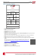
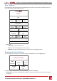
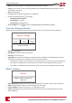
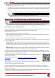
Table Of Contents
- Disclaimers
- Support and Contact Information
- Revision History
- HANDLING AND SAFETY INSTRUCTIONS
- IMPORTANT SAFETY INSTRUCTIONS
- Chapter 1: Introducing the SolarEdge Power Harvesting System
- Chapter 2: Installing the Power Optimisers
- Chapter 3: Installing the Inverter
- Chapter 4: Connecting the AC and the Strings to the Safety Switch
- Chapter 5: Activating, Commissioning and Configuring the System Using the Inverter SetApp
- Chapter 6: Setting Up Communication
- Appendix A: Errors and Troubleshooting
- Appendix B: Mechanical Specifications
- Appendix C: External Fan Maintenance and Replacement
- Appendix D: Replacing and Adding System Components
- Technical Specifications - Three Phase Inverters (North America)

l Energy:Thetotalenergyreadbythemeter.Thevaluedisplayedinthislinedependsonthemetertype
connectedtotheinverteranditslocation:
o
Ifabidirectionalmeterisconnectedattheconsumptionpoint,thisvalueistheconsumedenergy.
o
Ifthemeterisinstalledattheproductionconnectionpoint,thisvalueistheenergyproducedby
thesite.
o
Ifthemeterisinstalledatthegridconnectionpoint,thisvalueistheenergyexportedtothegrid.
NOTE
This data is accumulated according to an internal real-time clock.
Reporting and Monitoring Installation Data
NOTE
Monitoring the site requires connecting the inverter to the monitoring platform, using any of the wired or
wireless options available from SolarEdge. Refer to Setting Up Communication on page 51.
The Monitoring Platform
ThemonitoringplatformprovidesenhancedPVperformancemonitoringandyieldassurancethrough
immediatefaultdetectionandalertsatthemodule,stringandsystemlevel.
Usingtheplatform,youcan:
l Viewthelatestperformanceofspecificcomponents.
l Findunder-performingcomponents,suchasmodules,bycomparingtheirperformancetothatof
othercomponentsofthesametype.
l Pinpointthelocationofalertedcomponentsusingthephysicallayout.
Themonitoringplatformenablesaccessingsiteinformation,includingup-to-dateinformationviewedina
physicalorlogicalview:
l Logical Layout:Showsaschematictree-layoutofthecomponentsinthesystem,suchas:inverters,
strings,modules,metersandsensors,aswellastheirelectricalconnectivity.Thisviewenablesyouto
seewhichmodulesareconnectedineachstring,whichstringsareconnectedtoeachinverter,andso
on.
l Physical Layout:Providesabird'seyeviewoftheactualplacementofmodulesinthesite,andallows
pinpointissuestotheexactlocationofeachmoduleonavirtualsitemap.
Ifyoudonotreportthemappingoftheinstalledpoweroptimizers,themonitoringplatformwillshow
thelogicallayoutindicatingwhichpoweroptimizersareconnectedtowhichinverter,butwillnotshow
stringsorthephysicallocationofpoweroptimizers.
Themonitoringplatformincludesabuilt-inhelpsystem,thatguidesyouthroughthe
monitoringfunctionality.
Formoreinformation,refertohttps://www.solaredge.com/products/pv-
monitoring#/.
Creating Logical and Physical Layout using
Installation Information
Todisplayalogicallayout,inserttheinverterserialnumberinthenewsitecreatedinthemonitoring
platform.Whenthecommunicationbetweentheinverterandthemonitoringserverisestablished,the
logicallayoutisdisplayed.
Todisplayaphysicallayout,youneedtomapthelocationsoftheinstalledpoweroptimizers.Tomapthe
locations,useoneofthemethodsdescribedinthenextsections.
Chapter 5: Activating, Commissioning and Configuring the System Using the Inverter
-Three Phase System Installation Guide MAN-01-00527-1.1
49