
Install Manual

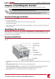
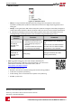
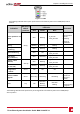
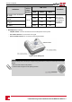
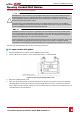
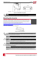

Table Of Contents
- Disclaimers
- Support and Contact Information
- Revision History
- HANDLING AND SAFETY INSTRUCTIONS
- IMPORTANT SAFETY INSTRUCTIONS
- Chapter 1: Introducing the SolarEdge Power Harvesting System
- Chapter 2: Installing the Power Optimisers
- Chapter 3: Installing the Inverter
- Chapter 4: Connecting the AC and the Strings to the Safety Switch
- Chapter 5: Activating, Commissioning and Configuring the System Using the Inverter SetApp
- Chapter 6: Setting Up Communication
- Appendix A: Errors and Troubleshooting
- Appendix B: Mechanical Specifications
- Appendix C: External Fan Maintenance and Replacement
- Appendix D: Replacing and Adding System Components
- Technical Specifications - Three Phase Inverters (North America)

Opening Conduit Drill Guides
Thissectiondescribeshowtoopendrillguides.
CAUTION!
SolarEdge does not permit opening or puncturing the Safety Switch in any location other than the pre-
defined drill guide locations, or otherwise altering the construction of the enclosure, as this may
compromise safety and will void the warranty. This includes, but is not limited to, the use of fasteners
like rivets, screws, nails, inserts, or pins.
For jurisdictions requiring field applied markings on the Safety Switch enclosure, such as labels or
placards that display PV system information, adhesive labels or placards that comply with ANSI Z535
and are compatible with the enclosure material may be used.
ATTENTION!
SolarEdge n'autorise pas l'ouverture or la perforation du commutateur de sécurité a tout endroit autre
que les emplacements de perforation guidés prédéfinis, ou la modification de l'enceinte électrique, car
cela compromettrait la sécurité et annulerait la garantie. Ceci inclus, sans être limité à, l'utilisation de
fixations comme des rivets, vis, clous, inserts ou des broches.
Pour les juridictions ou un marquage de sécurité est requis sur le couvercle du coupeur DC, tels que des
labels ou étiquettes qui figurent des information du système PV, des labels ou étiquettes adhésifs
compatibles avec ANSI Z535 peuvent être utilisés qui sont compatibles avec le matériau du couvercle.
Thisstepmaybeperformedbeforeoraftermountingtheinverter.
To open conduit drill guides:
1.
MovetheSafetySwitchandtheinverterON/OFFswitchtoOFF.
2.
LoosenthescrewsonthefrontcoveroftheSafetySwitch,asshownbelow:
Figure 13: Opening the Safety Switch cover
3. RemovetheSafetySwitchcover.
4. OpentherequiredACandDCconduitdrillguidesaccordingtotheconduitsusedintheinstallation:
Thedrillguidesarelocatedatthebottom,backandsidesoftheenclosure,eachwithtwosizes:¾''
and1''.Opentherequiredpair,takingcarenottointerferewithanyoftheinternalcomponents.Itis
recommendedtouseaUnibitdrill.
Chapter 3: Installing the Inverter
-Three Phase System Installation Guide MAN-01-00527-1.1
27