
Install Manual

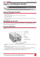
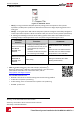
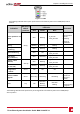
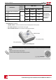
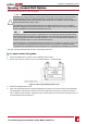
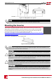
Table Of Contents
- Disclaimers
- Support and Contact Information
- Revision History
- HANDLING AND SAFETY INSTRUCTIONS
- IMPORTANT SAFETY INSTRUCTIONS
- Chapter 1: Introducing the SolarEdge Power Harvesting System
- Chapter 2: Installing the Power Optimisers
- Chapter 3: Installing the Inverter
- Chapter 4: Connecting the AC and the Strings to the Safety Switch
- Chapter 5: Activating, Commissioning and Configuring the System Using the Inverter SetApp
- Chapter 6: Setting Up Communication
- Appendix A: Errors and Troubleshooting
- Appendix B: Mechanical Specifications
- Appendix C: External Fan Maintenance and Replacement
- Appendix D: Replacing and Adding System Components
- Technical Specifications - Three Phase Inverters (North America)

Chapter 3: Installing the Inverter
Installtheinvertereitherbeforeorafterthemodulesandpoweroptimizershavebeeninstalled.
NOTE
l Use only copper conductors rated for a minimum of 90°C/ 194°F.
l For the SE10KUS, SE20KUS, SE33.3KUS three phase inverters where opposite polarity DC
conductors are routed in the same conduit, 1000V rated cables must be used.
Inverter Package Contents
l OneinverterwithSafetySwitch
l Onemountingbracket
l TwoAllenscrewsforfasteningtheinvertertothemountingbracket
l QuickInstallationguide
l Optional(forwirelesscommunicationtomonitoringplatform)-RFantennaandmountingbracket
l ACferritebeadkit
Identifying the Inverter
RefertothestickerontheinverterthatspecifiesitsSerial NumberanditsElectrical Ratings.Providethe
serialnumberwhencontactingSolarEdgesupport.Theserialnumberisalsorequiredwhenopeninga
newsiteinthemonitoringplatform.
Inverter Interfaces
Thefollowingfigureshowstheinverterconnectorsandcomponents,locatedatthebottomofthe
inverter.
Figure 9: Inverter Interfaces
l AC output:ACoutputgland,ACcableexternalgauge,M32(15-21mmdiameter)forconnectiontothe
grid
l AC and DC conduit entries:ConnectionpointsoftheSafetySwitch.
l Two communication glands,forconnectionofinvertercommunicationoptions.Eachglandhas
threeopenings.RefertoSettingUpCommunicationonpage51formoreinformation.
l Drain valve:Drainsanymoisturethatmaybeaccumulatedintheunit.
Chapter 3: Installing the Inverter
-Three Phase System Installation Guide MAN-01-00527-1.1
23