
Install Manual

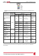
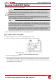
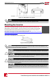
Table Of Contents
- Disclaimers
- Support and Contact Information
- Revision History
- HANDLING AND SAFETY INSTRUCTIONS
- IMPORTANT SAFETY INSTRUCTIONS
- Chapter 1: Introducing the SolarEdge Power Harvesting System
- Chapter 2: Installing the Power Optimisers
- Chapter 3: Installing the Inverter
- Chapter 4: Connecting the AC and the Strings to the Safety Switch
- Chapter 5: Activating, Commissioning and Configuring the System Using the Inverter SetApp
- Chapter 6: Setting Up Communication
- Appendix A: Errors and Troubleshooting
- Appendix B: Mechanical Specifications
- Appendix C: External Fan Maintenance and Replacement
- Appendix D: Replacing and Adding System Components
- Technical Specifications - Three Phase Inverters (North America)

Step 4: Verifying Proper Power Optimiser
Connection
Whenamoduleisconnectedtoapoweroptimizer,thepoweroptimizeroutputsasafevoltageof1V
(±0.1V).Therefore,thetotalstringvoltageshouldequal1Vtimesthenumberofpoweroptimizers
connectedinseriesinthestring.Forexample,if10poweroptimizersareconnectedinastring,then10V
shouldbeproduced.
MakesurethePVmodulesareexposedtosunlightduringthisprocess.Thepoweroptimizerwillonlyturn
ONifthePVmoduleprovidesatleast2W.
InSolarEdgesystems,duetotheintroductionofpoweroptimizersbetweenthePVmodulesandthe
inverter,theshortcircuitcurrentI
SC
andtheopencircuitvoltageV
OC
holddifferentmeaningsfrom
thoseintraditionalsystems.
FormoreinformationabouttheSolarEdgesystem’sstringvoltageandcurrent,referto
theV
OC
andI
SC
inSolarEdgeSystemsTechnicalNote,availableontheSolarEdgewebsiteat:
https://www.solaredge.com/sites/default/files/isc_and_voc_in_solaredge_sytems_
technical_note.pdf.
To verify proper power optimizer connection:
Measurethevoltageofeachstringindividuallybeforeconnectingittotheotherstringsortotheinverter.
Verifycorrectpolaritybymeasuringthestringpolaritywithavoltmeter.Useavoltmeterwithatleast
0.1Vmeasurementaccuracy.
NOTE
Since the inverter is not yet operating, you may measure the string voltage and verify correct polarity
on the DC wires inside the Safety Switch.
Fortroubleshootingpoweroptimizeroperationproblems,refertoPowerOptimizerTroubleshootingon
page64.
-Three Phase System Installation Guide MAN-01-00527-1.1
22
Step 4: Verifying Proper Power Optimiser Connection