
Install Manual

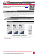
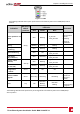
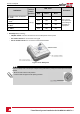
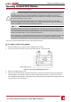
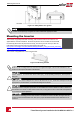
Table Of Contents
- Disclaimers
- Support and Contact Information
- Revision History
- HANDLING AND SAFETY INSTRUCTIONS
- IMPORTANT SAFETY INSTRUCTIONS
- Chapter 1: Introducing the SolarEdge Power Harvesting System
- Chapter 2: Installing the Power Optimisers
- Chapter 3: Installing the Inverter
- Chapter 4: Connecting the AC and the Strings to the Safety Switch
- Chapter 5: Activating, Commissioning and Configuring the System Using the Inverter SetApp
- Chapter 6: Setting Up Communication
- Appendix A: Errors and Troubleshooting
- Appendix B: Mechanical Specifications
- Appendix C: External Fan Maintenance and Replacement
- Appendix D: Replacing and Adding System Components
- Technical Specifications - Three Phase Inverters (North America)

6. Recordpoweroptimizerserialnumbersandlocations,asdescribedinReportingandMonitoring
InstallationDataonpage49.
Step 2: Connecting a PV Module to a Power
Optimiser
NOTE
Images are for illustration purposes only. Refer to the label on the product to identify the plus and
minus input and output connectors.
Foreachofthepoweroptimizers:
l ConnectthePlus(+)outputconnectorofthemoduletothePlus(+)inputconnectorofthepower
optimizer.
l ConnecttheMinus(-)outputconnectorofthemoduletotheMinus(-)inputconnectorofthe
poweroptimizer.
Figure 7: Power optimizer connectors
-Three Phase System Installation Guide MAN-01-00527-1.1
20
Step 2: Connecting a PV Module to a Power Optimiser