
Install Manual
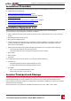
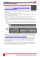
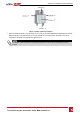
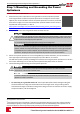
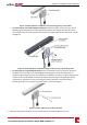
Table Of Contents
- Disclaimers
- Support and Contact Information
- Revision History
- HANDLING AND SAFETY INSTRUCTIONS
- IMPORTANT SAFETY INSTRUCTIONS
- Chapter 1: Introducing the SolarEdge Power Harvesting System
- Chapter 2: Installing the Power Optimisers
- Chapter 3: Installing the Inverter
- Chapter 4: Connecting the AC and the Strings to the Safety Switch
- Chapter 5: Activating, Commissioning and Configuring the System Using the Inverter SetApp
- Chapter 6: Setting Up Communication
- Appendix A: Errors and Troubleshooting
- Appendix B: Mechanical Specifications
- Appendix C: External Fan Maintenance and Replacement
- Appendix D: Replacing and Adding System Components
- Technical Specifications - Three Phase Inverters (North America)

Installation Guidelines
l Frame-mountedpoweroptimizersaremounteddirectlyonthemoduleframe,
regardlessofrackingsystem(rail-lessorwithrails).Forinstallationofframe-mounted
poweroptimizers,refertohttp://www.solaredge.com/sites/default/files/installing_
frame_mounted_power_optimizers.pdf.
l Thestepsinthischapterrefertomoduleadd-onpoweroptimizers.Forsmart
modules,startfromStep3:ConnectingPowerOptimizersinStringsonpage21Step3:
ConnectingPowerOptimizersinStringsonpage21.Alsorefertothedocumentationsuppliedwiththe
smartmodules.
l Thepoweroptimizercanbeplacedinanyorientation.
l Ifconnectingmoremodulesthanoptimizerinputsinparallel,useabranchcable.Somecommercial
poweroptimizermodelshaveadualinput.
l Positionthepoweroptimizercloseenoughtoitsmodulesothattheircablescanbeconnected.
l Makesuretousepoweroptimizersthathavetherequiredoutputconductorlength:
o
Donotuseextensioncablesbetweenamoduleandapoweroptimizer,betweentwomodules
connectedtothesameoptimizer,orbetweentwooptimizersotherthaninthecasesspecified
below.
o
Youcanuseextensioncablesbetweenpoweroptimizersonlyfromrowtorow,aroundobstacles
withinarow,andfromtheendofthestringtotheinverter,aslongasthemaximumdistanceis
notexceeded.
NOTE
l
The total conductor length of the string (excluding power optimizers’ conductors; including
home runs and necessary extensions between optimizers) should not exceed the following:
Inverter model Total conductor length ( from DC+ to DC- of the inverter)
SE9KUS, SE10KUS, SE20KUS 1000 ft. /300 m
SE14.4KUS, SE33.3KUS 2300 ft./ 700 m
l Use at least 11 AWG/ 4 mm² DC cables.
l Theminimumandmaximumstringlengthguidelinesarestatedinthepoweroptimizerdatasheets.
RefertotheDesignerforstringlengthverification.TheDesignerisavailableontheSolarEdgewebsite
athttps://www.solaredge.com/us/products/installer-tools/designer#/.
l Completelyshadedmodulesmaycausetheirpoweroptimizerstotemporarilyshutdown.Thiswill
notaffecttheperformanceoftheotherpoweroptimizersinthestring,aslongastheminimum
numberofunshadedpoweroptimizersconnectedinastringofmodulesismet.Ifundertypical
conditionsfewerthantheminimumoptimizersareconnectedtounshadedmodules,addmore
optimizerstothestring.
l Equipmentgroundingtighteningtorques:4-6AWG:45lb-in,8AWG:40lb-in,10-14AWG:35lb-in.
l Toallowforheatdissipation,maintaina2.5cm/1"clearancedistancebetweenthepoweroptimizer
andothersurfaces,onallsidesexceptthemountingbracketside.
-Three Phase System Installation Guide MAN-01-00527-1.1
16
Installation Guidelines