
Installation Guide


Table Of Contents
- Disclaimers
- Support and Contact Information
- Revision History
- Contents
- HANDLING AND SAFETY INSTRUCTIONS
- IMPORTANT SAFETY INSTRUCTIONS
- Chapter 1: Introducing the SolarEdge Power Harvesting System
- Chapter 2: Installing the Power Optimizers
- Chapter 3: Installing the Inverter
- Chapter 4: Connecting the AC and the Strings to the Safety Switch
- Chapter 5: Commissioning the Installation
- Chapter 6: User Interface
- Chapter 7: Setting Up Communication
- Appendix A: Errors and Troubleshooting
- Appendix B: Mechanical Specifications
- Appendix C: External Fan Maintenance and Replacement
- Appendix D: Replacing and Adding System Components
- Appendix E: Determining the Circuit Breaker Size
- Technical Specifications - Single Phase Inverters (North America)
- Technical Specifications - Three Phase Inverters (North America)
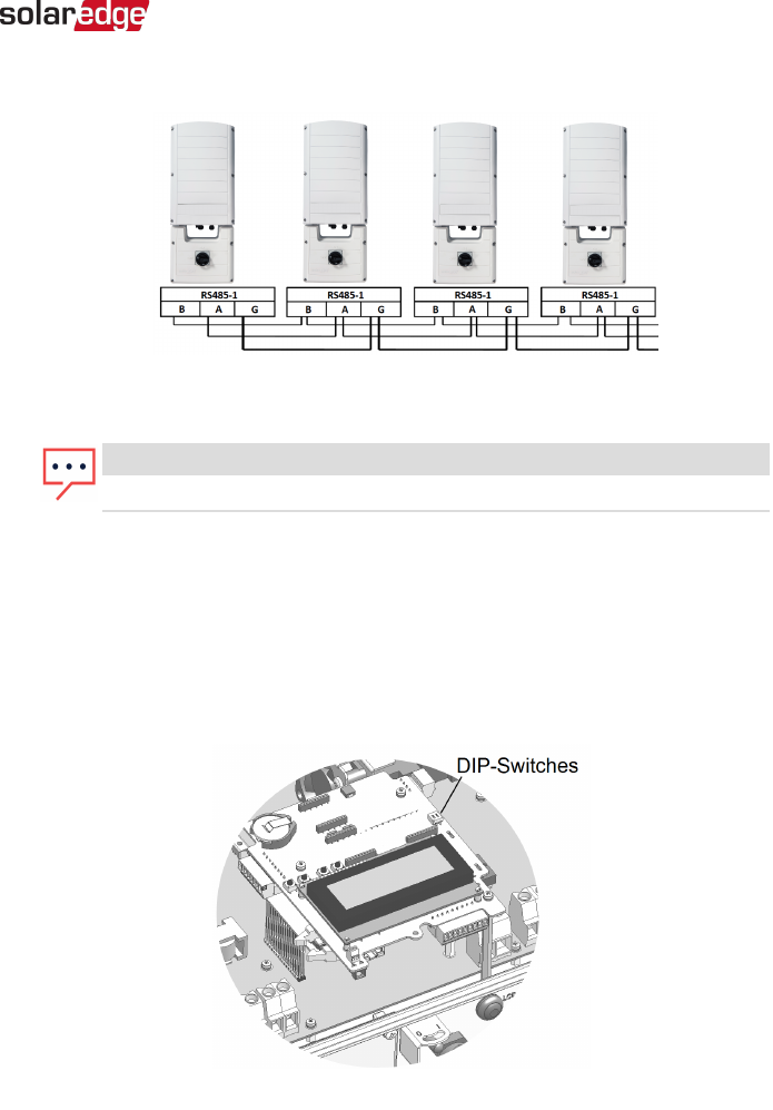
figure shows this connection schema:
Figure 36: Connecting the inverters in a chain
NOTE
Do not cross-connect B, A and G wires.
7. Tighten the terminal block screws.
8. Check that the wires are fully inserted and cannot be pulled out easily.
9.
Push the RS485 terminal block firmly all the way into the connector on the right side
of the communication board.
10.
Terminate the first and last SolarEdge device in the chain by switching a termination
DIP-switch inside the inverter to ON (move the left switch up). The switch is located
on the communication board and is marked SW7SW1.
Figure 37: RS485 termination switch
Chapter 7: Setting Up Communication 93
Three Phase System Installation Guide MAN-01-00002-4.3