
Installation Guide


Table Of Contents
- Disclaimers
- Support and Contact Information
- Revision History
- Contents
- HANDLING AND SAFETY INSTRUCTIONS
- IMPORTANT SAFETY INSTRUCTIONS
- Chapter 1: Introducing the SolarEdge Power Harvesting System
- Chapter 2: Installing the Power Optimizers
- Chapter 3: Installing the Inverter
- Chapter 4: Connecting the AC and the Strings to the Safety Switch
- Chapter 5: Commissioning the Installation
- Chapter 6: User Interface
- Chapter 7: Setting Up Communication
- Appendix A: Errors and Troubleshooting
- Appendix B: Mechanical Specifications
- Appendix C: External Fan Maintenance and Replacement
- Appendix D: Replacing and Adding System Components
- Appendix E: Determining the Circuit Breaker Size
- Technical Specifications - Single Phase Inverters (North America)
- Technical Specifications - Three Phase Inverters (North America)
Communication Connectors
Two communication glands are used for connection of the various communication
options. Each gland has three openings. The table below describes the functionality of
each opening. Unused openings should remain sealed.
Gland# Opening Functionality Cable size (diameter)
1 (PG16)
One small External antenna cable 2-4 mm
Two large
Ethernet connection
(CAT5/6), ZigBee, or
Cellular
4.5-7 mm
2 (PG13.5) All three RS485 2.5-5 mm
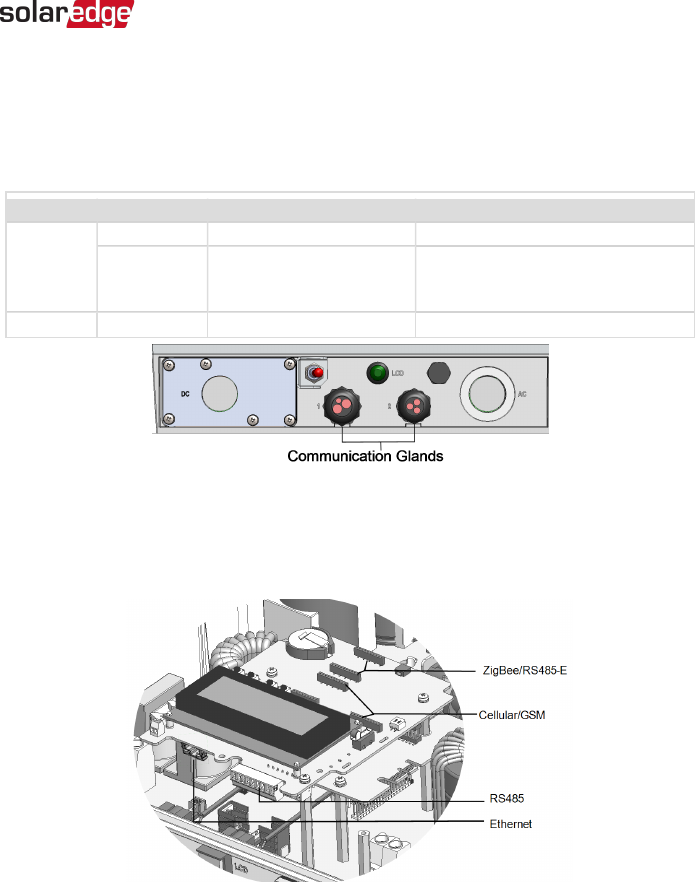
Figure 28: Communication Glands
The communication board has a standard RJ45 terminal block for Ethernet connection,
and a 9-pin terminal block for RS485 connection, as shown below:
Figure 29: Internal connectors
Chapter 7: Setting Up Communication 85
Three Phase System Installation Guide MAN-01-00002-4.3