
Installation Guide


Table Of Contents
- Disclaimers
- Support and Contact Information
- Revision History
- Contents
- HANDLING AND SAFETY INSTRUCTIONS
- IMPORTANT SAFETY INSTRUCTIONS
- Chapter 1: Introducing the SolarEdge Power Harvesting System
- Chapter 2: Installing the Power Optimizers
- Chapter 3: Installing the Inverter
- Chapter 4: Connecting the AC and the Strings to the Safety Switch
- Chapter 5: Commissioning the Installation
- Chapter 6: User Interface
- Chapter 7: Setting Up Communication
- Appendix A: Errors and Troubleshooting
- Appendix B: Mechanical Specifications
- Appendix C: External Fan Maintenance and Replacement
- Appendix D: Replacing and Adding System Components
- Appendix E: Determining the Circuit Breaker Size
- Technical Specifications - Single Phase Inverters (North America)
- Technical Specifications - Three Phase Inverters (North America)
AVERTISSEMENT!
Si un optimiseur à double entrées est utilisé et que certaines entrées ne sont
pas connectées, fermez ces entrées avec la paire de couvercles fournie.
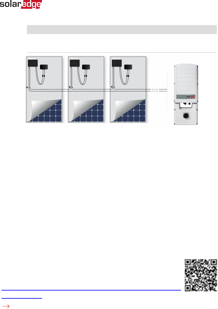
Figure 8: Power optimizers connected in series
3.
If you intend to monitor the installation, using the monitoring platform, record the
physical location of each power optimizer, as described in
Creating Logical and
Physical Layout using Installation Information
on page 58.
Step 4: Verifying Proper Power Optimizer Connection
When a module is connected to a power optimizer, the power optimizer outputs a safe
voltage of 1V (±0.1V). Therefore, the total string voltage should equal 1V times the
number of power optimizers connected in series in the string. For example, if 10 power
optimizers are connected in a string, then 10V should be produced.
Make sure the PVmodules are exposed to sunlight during this process. The power
optimizer will only turn ON if the PVmodule provides at least 2W.
In SolarEdge systems, due to the introduction of poweroptimizers between the PV
modules and the inverter, the short circuit current I
SC
and the open circuit voltage V
OC
hold different meanings from those in traditional systems.
For more information about the SolarEdge system’s string voltage and
current, refer to the
V
OC
and I
SC
in SolarEdge Systems Technical Note
,
available on the SolarEdge website at:
https://www.solaredge.com/sites/default/files/isc_and_voc_in_solaredge_sytems_
technical_note.pdf .
To verify proper power optimizer connection:
Chapter 2: Installing the Power Optimizers 29
Three Phase System Installation Guide MAN-01-00002-4.3