
Installation Guide


Table Of Contents
- Disclaimers
- Support and Contact Information
- Revision History
- Contents
- HANDLING AND SAFETY INSTRUCTIONS
- IMPORTANT SAFETY INSTRUCTIONS
- Chapter 1: Introducing the SolarEdge Power Harvesting System
- Chapter 2: Installing the Power Optimizers
- Chapter 3: Installing the Inverter
- Chapter 4: Connecting the AC and the Strings to the Safety Switch
- Chapter 5: Commissioning the Installation
- Chapter 6: User Interface
- Chapter 7: Setting Up Communication
- Appendix A: Errors and Troubleshooting
- Appendix B: Mechanical Specifications
- Appendix C: External Fan Maintenance and Replacement
- Appendix D: Replacing and Adding System Components
- Appendix E: Determining the Circuit Breaker Size
- Technical Specifications - Single Phase Inverters (North America)
- Technical Specifications - Three Phase Inverters (North America)
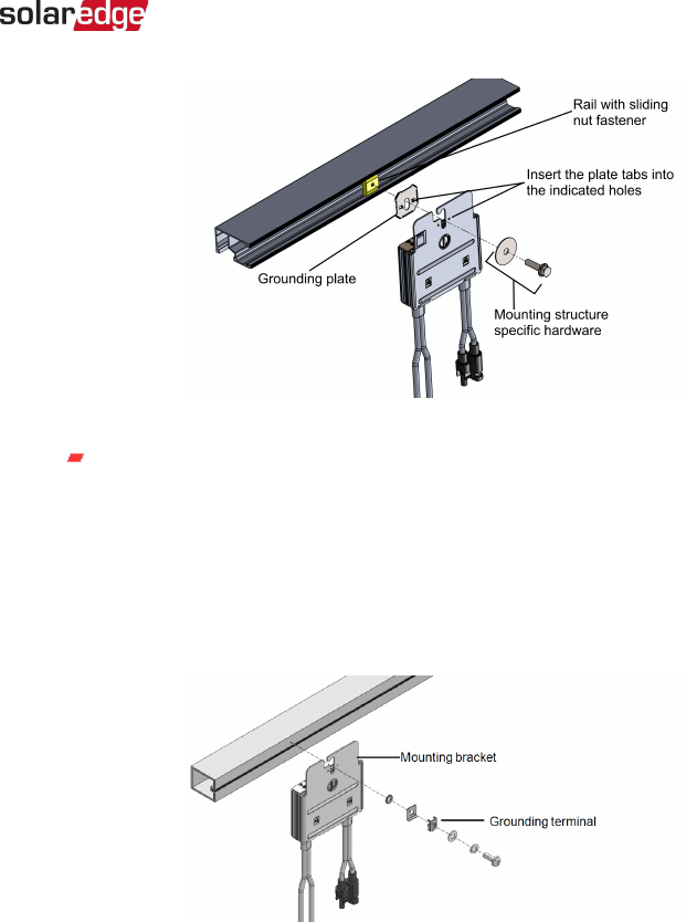
Figure 5: Power optimizer installation and grounding using a grounding plate
For mounting on un-grounded structures (such as a wooden structure): If
the star washer or the plate cannot be used, use the SolarEdge grounding
lug (purchased separately)with an equipment-grounding conductor
according to the supplied instructions. The grounding terminal accepts a
wire size of 6-14 AWG, and must be sized for equipment grounding per NEC
250.122 requirements. Tighten the screws connecting the power optimizer to
the frame and the grounding terminal screw. Apply torque of 9.5 N*m / 7
lb*ft. See
Figure 6
.
Figure 6: Power optimizer grounding terminal
5. Verify that each power optimizer is securely attached to the module support
structure.
6. Record power optimizer serial numbers and locations, as described in
Step 4:
Reporting and Monitoring Installation Data
on page 57.
Chapter 2: Installing the Power Optimizers 27
Three Phase System Installation Guide MAN-01-00002-4.3