
Installation Guide


Table Of Contents
- Disclaimers
- Support and Contact Information
- Revision History
- Contents
- HANDLING AND SAFETY INSTRUCTIONS
- IMPORTANT SAFETY INSTRUCTIONS
- Chapter 1: Introducing the SolarEdge Power Harvesting System
- Chapter 2: Installing the Power Optimizers
- Chapter 3: Installing the Inverter
- Chapter 4: Connecting the AC and the Strings to the Safety Switch
- Chapter 5: Commissioning the Installation
- Chapter 6: User Interface
- Chapter 7: Setting Up Communication
- Appendix A: Errors and Troubleshooting
- Appendix B: Mechanical Specifications
- Appendix C: External Fan Maintenance and Replacement
- Appendix D: Replacing and Adding System Components
- Appendix E: Determining the Circuit Breaker Size
- Technical Specifications - Single Phase Inverters (North America)
- Technical Specifications - Three Phase Inverters (North America)
Installing a New Safety Switch
1. Open the conduit drill guides of the new Safety Switch (refer to
Opening Conduit
Drill Guides
on page 35).
2. Position the new Safety Switch below the inverter and from the inside of the inverter
grab the AC and DC wires extending from the switch conduits.
3. Attach the Safety Switch with its bracket to the wall and slightly close the screws. Do
not over tighten.
4. Securely screw the two conduit nuts onto the conduit ends in the inverter. Verify
proper conduit sealing.
Connecting the Safety Switch to the Inverter
1. If ferrite beads were removed from the DC and AC wires, place them on the wires
and close them. Make sure the DC labeled ferrite bead is placed on the DC wires and
the AC labeled ferrite bead is placed on the AC wires.
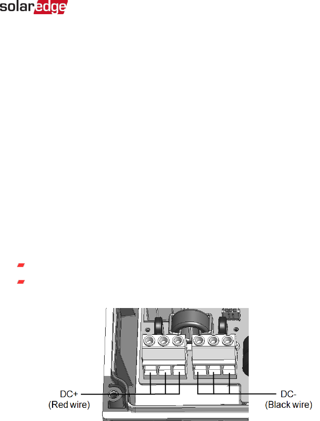
2. Connect the DC, as follows:
Connect the red wire to any of the DC+ terminals in the inverter.
Connect the black wire to any of the DC- terminals in the inverter.
Figure 45: DC terminals
3.
Connect the AC wires according to the labels on the ACterminal blocks, as follows:
Appendix D: Replacing and Adding System Components 107
Three Phase System Installation Guide MAN-01-00002-4.3