
Install Manual
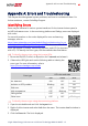
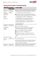
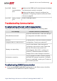


Table Of Contents
- Disclaimers
- Revision History
- HANDLING AND SAFETY INSTRUCTIONS
- IMPORTANT SAFETY INSTRUCTIONS
- Chapter 1: Overview
- Chapter 2: Installing the Power Optimizer
- Chapter 3: Installing the Inverter
- Chapter 4: Installing the Battery
- Chapter 5: Connecting the Inverter
- Chapter 6: Activating, Commissioning and Configuring the System
- Chapter 7: Setting Up Communication to the Monitoring Platform
- Appendix A: Errors and Troubleshooting
- Appendix B: Mechanical Specifications
- Appendix C: Replacing and Adding System Components
- Appendix D: Powering the LG Chem Battery Off and On
- Single Phase Energy Hub Inverter with Prism Technology - Technical Specificat...
- Support Contact Information

8. For the switch/router side, use a pre-crimped cable or use a crimper to prepare an
RJ45 communication connector: Insert the eight wires into the RJ45 connector in the
same order as above .
9. Connect the cable RJ45 connector to the RJ45 port of the Ethernet switch or router.
You can connect more than one inverter to the same switch/router or to different
switches/routers, as needed. Each inverter sends its monitored data independently
to the SolarEdge monitoring platform.
10.
The inverter is configured by default to LAN.
a. Make sure the ON/OFF/P switch is OFF.
b. Turn ON the AC to the inverter by turning ON the circuit breaker on the main
distribution panel.
c.
Turn ON the Connection Unit.
WARNING!
ELECTRICAL SHOCK HAZARD. Do not touch uninsulated wires when the
inverter cover is removed.
d.
Configure the connection as described in
Communication
on page 47.
NOTE
If your network has a firewall, you may need to configure it to enable
the connection to the following address:
Destination Address: prod.solaredge.com
TCP Port: 22222 (for incoming and outgoing data)
11. Verify the connection, as described in
Verifying the Connection
on page 60.
Verifying the Connection
After connecting and configuring a communication option, perform the following
steps to check that the connection to the monitoring server has been successfully
established.
1.
Go to Commissioning >Status.
2. In the Summary section, under Server Comm., make sure S_OK is displayed
together with the selected communication option.
3.
Scroll down to the Communication section and check that the communication
options are as required.
Single Phase Energy Hub Inverter with Prism Technology MAN-01-00671-1.2
60 Verifying the Connection