
Install Manual
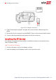
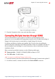

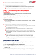

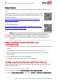
Table Of Contents
- Disclaimers
- Revision History
- HANDLING AND SAFETY INSTRUCTIONS
- IMPORTANT SAFETY INSTRUCTIONS
- Chapter 1: Overview
- Chapter 2: Installing the Power Optimizer
- Chapter 3: Installing the Inverter
- Chapter 4: Installing the Battery
- Chapter 5: Connecting the Inverter
- Chapter 6: Activating, Commissioning and Configuring the System
- Chapter 7: Setting Up Communication to the Monitoring Platform
- Appendix A: Errors and Troubleshooting
- Appendix B: Mechanical Specifications
- Appendix C: Replacing and Adding System Components
- Appendix D: Powering the LG Chem Battery Off and On
- Single Phase Energy Hub Inverter with Prism Technology - Technical Specificat...
- Support Contact Information

Device).
3.
Return to the previous screen and select Add Modbus Device > Battery.
4.
Verify the battery information by selecting Battery 1 è Battery Information.
To set up communication with the Energy Meter:
If you are setting up communication with the meter before the battery, first perform
Steps 1-3 above. After that, proceed with the steps below.
If the Backup Interface is installed as part of your system, configure the Backup
Interface's meter as described below.
1.
In the RS485-1 screen, select Add Modbus Device è Meter.
2.
Set the Energy Meter’s CT Rating according to the CT specifications. If the CT rating
value returns to 0, check communication with the CT.
3.
Select Meter 2 è Meter Function è Export+Import (E+I).
To set up communication with the Smart EVCharger
1. Access SetApp and select Commissioning > Site Communication.
2. Configure the Energy Hub inverter to be the leader by selecting RS485-2 > Protocol
> SolarEdge > SolarEdge Leader.
3.
Configure the Smart EVCharger to be the follower by selecting RS485-2 > Protocol
> Follower Detect.
Running a Battery Self-test
Run a battery self-test to check the battery's charge and discharge functionality.
To run a battery self-test:
1. Make sure the battery's circuit breaker switch is ON.
2.
Switch the inverter ON/OFF/P switch to ON.
3.
In SetApp, select Commissioning è Maintenance è Diagnostics è Self-Test è
Battery Self-Test è Run Test.
4.
Wait for all tests to complete and check the results in the summary table.
If any of the tests have failed, see the table below for possible solutions:
Chapter 6: Activating, Commissioning and Configuring the System 49
Single Phase Energy Hub Inverter with Prism Technology MAN-01-00671-1.2