
Install Manual
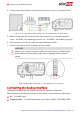
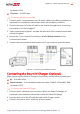
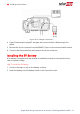
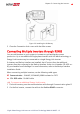
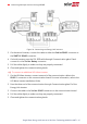

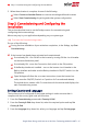

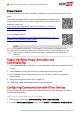
Table Of Contents
- Disclaimers
- Revision History
- HANDLING AND SAFETY INSTRUCTIONS
- IMPORTANT SAFETY INSTRUCTIONS
- Chapter 1: Overview
- Chapter 2: Installing the Power Optimizer
- Chapter 3: Installing the Inverter
- Chapter 4: Installing the Battery
- Chapter 5: Connecting the Inverter
- Chapter 6: Activating, Commissioning and Configuring the System
- Chapter 7: Setting Up Communication to the Monitoring Platform
- Appendix A: Errors and Troubleshooting
- Appendix B: Mechanical Specifications
- Appendix C: Replacing and Adding System Components
- Appendix D: Powering the LG Chem Battery Off and On
- Single Phase Energy Hub Inverter with Prism Technology - Technical Specificat...
- Support Contact Information

insulated or CAT5
12V power - 16 AWG cable
To connect the Backup Interface:
1.
Connect the AC, communication and 12V power cables to the Backup Interface, as
explained in the installation manual that comes with the Backup interface.
2. Connect the other end of the ACcable to the inverter, as explained in
Connecting
the Inverter to ACGrid
on page 37.
3. Open Communication gland 1 and pass the other end of the communication cable
through the gland.
4. Remove the 7-pin connector from the port labeled Backup Interface on the
communication board.
5.
Connect the communication cable wires to the 7-pin connector, as shown below.
Figure 21: Connecting the Backup Interface
Connecting the Smart EVCharger (Optional)
When connecting the Smart EVCharger to the inverter, use the following cable types:
AC - 14-4 AWG cable
Communication - 5-wire shielded twisted pair cable, 24 AWG (16-24 AWG), 600V
insulated or CAT5
To connect the Smart EVCharger:
1.
Connect the ACcable and communication cable to the Smart EVCharger, as
explained in the installation manual that comes with Smart EVCharger.
2. Pass the other end of the ACcable through the EV Charger conduit.
3.
Connect the wires to the ACterminals, as shown below.
Chapter 5: Connecting the Inverter 41
Single Phase Energy Hub Inverter with Prism Technology MAN-01-00671-1.2