
Install Manual
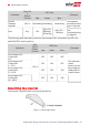
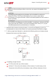
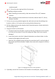
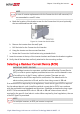
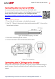

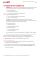
Table Of Contents
- Disclaimers
- Revision History
- HANDLING AND SAFETY INSTRUCTIONS
- IMPORTANT SAFETY INSTRUCTIONS
- Chapter 1: Overview
- Chapter 2: Installing the Power Optimizer
- Chapter 3: Installing the Inverter
- Chapter 4: Installing the Battery
- Chapter 5: Connecting the Inverter
- Chapter 6: Activating, Commissioning and Configuring the System
- Chapter 7: Setting Up Communication to the Monitoring Platform
- Appendix A: Errors and Troubleshooting
- Appendix B: Mechanical Specifications
- Appendix C: Replacing and Adding System Components
- Appendix D: Powering the LG Chem Battery Off and On
- Single Phase Energy Hub Inverter with Prism Technology - Technical Specificat...
- Support Contact Information

conduits as well.
4" (10 cm) from the right and left of the inverter.
If installing multiple inverters:
When installing inverters side by side, leave at least 20 cm (8") between
inverters.
When installing inverters one above of the other, leave at least 16" (40 cm)
between inverters.
3. Position the mounting bracket against the wall/ pole and mark the drilling hole
locations (refer to for inverter and mounting bracket dimensions).
4.
Drill the holes and mount the bracket. Verify that the bracket is firmly attached to
the mounting surface.
5.
Hang the inverter on the bracket:
a. Lift the inverter from the sides, or hold it at the top and bottom of the inverter
to lift the unit into place. Do not lift holding the Safety Switch as it may be
damaged.
b. Lower the inverter onto the U-shaped indentations, as shown below. Let the
inverter lay flat against the wall or pole.
c.
Insert the two supplied screws through the outer heat sink fin on both sides of
the inverter and into the bracket. Tighten the screws with a torque of 4.0 N*m /
2.9 lb.*ft.
Figure 13: Hanging the inverter on the brackets
6.
Optionally, secure the Connection Unit bracket to the wall/pole, using 3 screws:
Single Phase Energy Hub Inverter with Prism Technology MAN-01-00671-1.2
32 Mounting the Inverter