
Install Manual

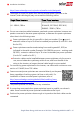
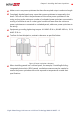
Table Of Contents
- Disclaimers
- Revision History
- HANDLING AND SAFETY INSTRUCTIONS
- IMPORTANT SAFETY INSTRUCTIONS
- Chapter 1: Overview
- Chapter 2: Installing the Power Optimizer
- Chapter 3: Installing the Inverter
- Chapter 4: Installing the Battery
- Chapter 5: Connecting the Inverter
- Chapter 6: Activating, Commissioning and Configuring the System
- Chapter 7: Setting Up Communication to the Monitoring Platform
- Appendix A: Errors and Troubleshooting
- Appendix B: Mechanical Specifications
- Appendix C: Replacing and Adding System Components
- Appendix D: Powering the LG Chem Battery Off and On
- Single Phase Energy Hub Inverter with Prism Technology - Technical Specificat...
- Support Contact Information

https://www.solaredge.com/us/products/installer-tools/designer#/.
The length of home-run cables from the first and last power optimizer to the
inverter (total cable length) may not exceed the following values:
Single Phase Inverters Three Phase Inverters
All - 1000 ft. /300 m
SE9KUS, SE20KUS - 1000 ft. /300 m
SE14.4KUS, SE17.3KUS, SE33.3KUS,
SE40KUS - 2300 ft. /700 m
Do not
use extension cables between a panel and a power optimizer, between two
panels connected to the same power optimizer, or between two power optimizers
other than in the following cases:
Power optimizers with the 4-type suffix in their part number (Pxxx-4xxxxxx) -
extension cables of up to 16 m can be installed per optimizer (8 m for DC+ and
8 m for DC-).
Power optimizers manufactured starting from working week 42, 2019, as
indicated in the serial number (Example:S/N SJ5019A-xxxxxxxx - working week
50, 2019) - extension cables of up to 16 m can be installed per power optimizer
(8 m for DC+ and 8 m for DC-).
Extension cables can be installed between power optimizers only from row to
row, around obstacles or pathways within a row, and from the end of the
string to the inverter, as long as the total cable length is not exceeded.
For connecting power optimizers to the inverter, use cables with a minimum cross-
section of 11 AWG/ 4 mm² DC cables.
Frame-mounted power optimizers are mounted directly on the panel
frame, regardless of racking system (rail-less or with rails). For
installation of frame-mounted power optimizers, refer to
http://www.solaredge.com/sites/default/files/installing_frame_
mounted_power_optimizers.pdf.
The power optimizer can be placed in any orientation.
If connecting more panels than power optimizer inputs in parallel, use a branch
cable. Some commercial power optimizer models have a dual input.
Position the power optimizer close enough to its panel so that their cables can be
connected.
Single Phase Energy Hub Inverter with Prism Technology MAN-01-00671-1.2
18 Installation Guidelines