Installation Guide Single Phase Energy Hub Inverter with Prism Technology with SetApp Configuration Version 1.
Disclaimers 1 Disclaimers Important Notice Copyright © SolarEdge Inc. All rights reserved. No part of this document may be reproduced, stored in a retrieval system or transmitted, in any form or by any means, electronic, mechanical, photographic, magnetic or otherwise, without the prior written permission of SolarEdge Inc. The material furnished in this document is believed to be accurate and reliable. However, SolarEdge assumes no responsibility for the use of this material.
2 FCC Compliance Connect the equipment into an outlet on a circuit different from that to which the receiver is connected. Consult the dealer or an experienced radio/TV technician for help. Changes or modifications not expressly approved by the party responsible for compliance may void the user’s authority to operate the equipment. Single Phase Energy Hub Inverter with Prism Technology MAN-01-00671-1.
Revision History Revision History Version 1.2 (May 2020) Product name changed to Single Phase Energy Hub Inverter with Prism Technology. Updated "Activating, Commissioning and Configuring the System" on page 45. Added Connecting Multiple Inverters through RS485 on page 43. Added Energy Hub Inverter Troubleshooting on page 62. Version 1.1 (February 2020) Added Installing Conduits on page 36. Editorial changes Version 1.
4 Revision History Contents Disclaimers Important Notice FCC Compliance 1 1 1 Revision History 3 HANDLING AND SAFETY INSTRUCTIONS Safety Symbols Information 6 6 IMPORTANT SAFETY INSTRUCTIONS 7 Chapter 1: Overview The Energy Hub Solution Components Installation Equipment List Inverter Transport and Storage 12 12 13 14 Chapter 2: Installing the Power Optimizer Safety Package Contents Installation Guidelines Step 1: Mounting and Grounding the Power Optimizers Step 2: Connecting a PV panel to a Power
Revision History 5 Step 2: Commissioning and Configuring the Installation Step 3: Verifying Proper Activation and Commissioning Configuring Communication with Other Devices Running a Battery Self-test Enabling StorEdge Applications Reporting and Monitoring Installation Data 46 48 48 49 50 51 Chapter 7: Setting Up Communication to the Monitoring Platform Communication Options Communication Connectors Removing the Inverter Cover Removing the Connection Unit Cover Creating an Ethernet (LAN) Connection Veri
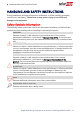
6 HANDLING AND SAFETY INSTRUCTIONS HANDLING AND SAFETY INSTRUCTIONS During installation, testing and inspection, adherence to all the handling and safety instructions is mandatory. Failure to do so may result in injury or loss of life and damage to the equipment. Safety Symbols Information The following safety symbols are used in this document. Familiarize yourself with the symbols and their meaning before installing or operating the system. WARNING! Denotes a hazard.
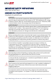
IMPORTANT SAFETY INSTRUCTIONS 7 IMPORTANT SAFETY INSTRUCTIONS SAVE THESE INSTRUCTIONS CONSIGNES DE SÉCURITÉ IMPORTANTES CONSERVEZ CES INSTRUCTIONS WARNING! The inverter cover must be opened only after switching the inverter ON/OFF/P switch located at the bottom of the inverter to OFF. This disables the DC voltage inside the inverter. Wait five minutes before opening the cover. Otherwise, there is a risk of electric shock from energy stored in the capacitors.
8 IMPORTANT SAFETY INSTRUCTIONS WARNING! The inverter input and output circuits are isolated from the enclosure. This system does not include an isolation transformer and should be installed with an ungrounded PV array in accordance with the requirements of NEC Articles 690.35 and 690.43 National Electric Code, ANSI/NFPA 70, 2011 (and Canadian Electrical Code, Part I, for installations in Canada).
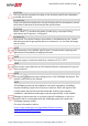
IMPORTANT SAFETY INSTRUCTIONS CAUTION! This unit must be operated according to the technical specification datasheet provided with the unit. ATTENTION! Cette unité doit être utilisée selon les spécifications de fonctionnement, comme décrit dans la dernière fiche technique des spécifications. CAUTION! HEAVY OBJECT. To avoid muscle strain or back injury, use proper lifting techniques, and if required - a lifting aid. ATTENTION! Objet lourd.
10 IMPORTANT SAFETY INSTRUCTIONS WARNING! Before operating the system, ensure that the been grounded properly. AVERTISSEMENT! Avant d'utiliser l'onduleur monophasé, assurez-vous que l'onduleur est correctement mis à la terre. WARNING! When handling the storage system battery, adhere to all manufacturer safety instructions. AVERTISSEMENT! Durant la manipulation de la batterie, adhérez à toutes les instructions de sécurité du fabricant.
IMPORTANT SAFETY INSTRUCTIONS fourni avec le produit. NOTE The battery used must be NRTL certified. NOTE For battery decommissioning and disposal, follow the manufacturer requirements and instructions. Single Phase Energy Hub Inverter with Prism Technology MAN-01-00671-1.
12 Chapter 1: Overview Chapter 1: Overview The single phase Energy Hub inverter with prism technology is SolarEdge's all-in-one solution that uses a single phase DC optimized inverter to manage and monitor solar power generation, energy storage, EV charging and smart energy devices. When installed with a battery and the Backup Interface, homeowners are automatically provided with backup power in the event of grid interruption to power home loads.
Chapter 1: Overview Figure 1: Energy Hub system components NOTE Additional SolarEdge inverters (without batteries) can be connected over RS485. The inverters will participate in export limitation, Smart Energy Management and backup operation. PV modules connected to power optimizers are not mandatory for charge/ discharge profile programming. Installation Equipment List Standard tools can be used during the installation of the SolarEdge system.
14 Inverter Transport and Storage Standard flat-head screwdrivers set Non-contact voltage detector Cordless drill (with a torque clutch) or screwdriver and bits suitable for the surface on which the inverter and optimizers will be installed and for opening the Connection Unit drill guides. Use of an impact driver is not allowed.
Chapter 2: Installing the Power Optimizer 15 Chapter 2: Installing the Power Optimizer Safety WARNING! The metallic enclosure of the power optimizer must be grounded in accordance with the product's listing and local and national codes. AVERTISSEMENT! L'enceinte métallique de l’optimiseur de puissance doit être mise à la terre en accord avec les régulations locales et nationales.
16 Safety CAUTION! All PV panels must be connected to a power optimizer. ATTENTION! Tous les modules doivent être connectés à un optimiseur de puissance. CAUTION! If you intend to mount the optimizers directly to the panel or panel frame, first consult the panel manufacturer for guidance regarding the mounting location and the impact, if any, on panel warranty. Drilling holes in the panel frame should be done according to the panel manufacturer instructions.
Chapter 2: Installing the Power Optimizer 17 ATTENTION! Les connecteurs du module doivent être mécaniquement compatibles avec les optimiseurs de puissance. Sinon, le système SolarEdge installé peut être dangereux ou causer des problèmes fonctionnels, tels que les défauts de terre, qui peuvent provoquer un arrêt de l’onduleur.
18 Installation Guidelines https://www.solaredge.com/us/products/installer-tools/designer#/. The length of home-run cables from the first and last power optimizer to the inverter (total cable length) may not exceed the following values: Single Phase Inverters Three Phase Inverters SE9KUS, SE20KUS - 1000 ft. /300 m All - 1000 ft. /300 m SE14.4KUS, SE17.3KUS, SE33.3KUS, SE40KUS - 2300 ft.
Chapter 2: Installing the Power Optimizer 19 Make sure to use power optimizers that have the required output conductor length. Completely shaded panels may cause their power optimizers to temporarily shut down. This will not affect the performance of the other power optimizers in the string, as long as the minimum number of unshaded power optimizers connected in a string of modules is met.
20 Step 1: Mounting and Grounding the Power Optimizers Step 1: Mounting and Grounding the Power Optimizers (1) For each of the power optimizers : 1. Determine the power optimizer mounting location and use the power optimizer mounting brackets to attach the power optimizer to the support structure (See Figure 3). It is recommended to mount the power optimizer in a location protected from direct sunlight.
Chapter 2: Installing the Power Optimizer (1) 4. Use the following methods 21 to ground the power optimizer: WARNING! The metallic enclosure of the power optimizer must be grounded in accordance with the requirements of the local and national codes. AVERTISSEMENT! L'enceinte métallique de l’optimiseur de puissance doit être mise à la terre en accord avec les régulations locales et nationales.
22 Step 1: Mounting and Grounding the Power Optimizers For mounting on rails with sliding nut fasteners: If the star washer cannot be used, use the SolarEdge grounding plate (purchased separately) between the railing and the flat side of the mounting bracket. Use mounting specific hardware as needed. Apply a torque of 9.5 N*m / 7 lb*ft. See Figure 4.
Chapter 2: Installing the Power Optimizer 23 5. Verify that each power optimizer is securely attached to the panel support structure. 6. Record power optimizer serial numbers and locations, as described in Reporting and Monitoring Installation Data on page 51. Step 2: Connecting a PV panel to a Power Optimizer NOTE Images are for illustration purposes only. Refer to the label on the product to identify the plus and minus input and output connectors.
24 Step 4: Verifying Proper Power Optimizer Connection WARNING! If using a dual-input power optimizer and some inputs are not used, seal the unused input connectors with the supplied pair of seals. AVERTISSEMENT! Si un optimiseur à double entrées est utilisé et que certaines entrées ne sont pas connectées, fermez ces entrées avec la paire de couvercles fournie. Figure 7: Power optimizers connected in series 3.
Chapter 2: Installing the Power Optimizer 25 Measure the voltage of each string individually before connecting it to the other strings or to the inverter. Verify correct polarity by measuring the string polarity with a voltmeter. Use a voltmeter with at least 0.1V measurement accuracy. NOTE Since the inverter is not yet operating, you may measure the string voltage and verify correct polarity on the DC wires inside the Connection Unit.
26 Chapter 3: Installing the Inverter Chapter 3: Installing the Inverter Install the inverter either before or after the panels and power optimizers have been installed. Inverter Package Contents One Energy Hub inverter One mounting bracket Two Allen screws for fastening the inverter to the mounting bracket One 9V battery Installation guide Identifying the Inverter Refer to the sticker on the inverter that specifies its Serial Number and its Electrical Ratings.
Chapter 3: Installing the Inverter 27 AC conduit entry - For AC connection to the grid or Backup Interface PV conduit entry - For DC connection to SolarEdge Power Optimizers EV conduit entry - For AC connection to the Standalone EV Charger Battery conduit entry - For DC connection to the battery DC Safety switch - connects and disconnects the DC power to the system Two communication glands: for connection of inverter communication options. Each gland has three openings.
28 Inverter Interfaces P - Moving and releasing the switch allows viewing system information via the LEDs, and performing the following functions: P Position Duration Switch moved to P for 2 seconds, then released. Function Displays (via LEDs) production information for 5 seconds, or error type indications (if exist) for 5 seconds. Comments While the switch is in P, all LEDs are ON. When the switch is released all LEDs turn OFF for 0.
Chapter 3: Installing the Inverter 29 Figure 10: LEDs The following table describes system performance information by LED color and ON/OFF/P switch position.
30 Mounting the Inverter Indication ON/ OFF/ P Switch Position Inverter firmware upgrade ON / P Error Any LED Color Comment Red Green Blue Alternating Alternating ON Alternating ON/ OFF/ Blinking/ Flickering ON/ OFF / Blinking The upgrade process can take up to 5 minutes Refer to Errors and Troubleshooting on page 61 The following table describes production percentage of AC information by LED color and ON/OFF/P switch position.
Chapter 3: Installing the Inverter 31 NOTE Make sure the mounting surface or structure can support the weight of the inverter. CAUTION! SolarEdge inverters and power optimizers can be installed at a minimum distance of 50 m/ 164 ft from the shoreline of an ocean or other saline environment, as long as there are no direct salt water splashes on the inverter or power optimizer.
32 Mounting the Inverter conduits as well. 4" (10 cm) from the right and left of the inverter. If installing multiple inverters: When installing inverters side by side, leave at least 20 cm (8") between inverters. When installing inverters one above of the other, leave at least 16" (40 cm) between inverters. 3. Position the mounting bracket against the wall/ pole and mark the drilling hole locations (refer to for inverter and mounting bracket dimensions). 4. Drill the holes and mount the bracket.
Chapter 3: Installing the Inverter 33 NOTE In case of inverter replacement with the Connection Unit still mounted, it is recommended to use all 3 holes. a. Mark the location of the bracket screw for the Connection Unit, and optionally the two additional bracket holes. Figure 14: Connection Unit bracket b. Remove the inverter from the wall/ pole. c. Drill the hole for the Connection Unit bracket. d. Hang the inverter on the mounted brackets. e. Fasten the Connection Unit bracket using a standard bolt. 7.
34 Selecting a Residual Current Device (RCD) In installations where the local electric code requires an RCD with a lower leakage setting, the discharge current might result in nuisance tripping of the external RCD. The following steps are recommended to avoid nuisance tripping of the external RCD: Select the appropriate RCD for correct operation of the installation: An RCD with a rating of 30 mA may actually trip at a leakage as low as 15 mA (according to IEC 61008).
Chapter 4: Installing the Battery 35 Chapter 4: Installing the Battery Install the battery in accordance with the manufacturer instructions. In addition, follow these guidelines: Make sure the battery's circuit breaker switch is OFF. For easy access to battery connectors, it is recommended to connect the cables to the battery and to set all battery DIP switches to their correct positions before mounting the battery. Measure the necessary length between the and the battery for all cables.
36 Chapter 5: Connecting the Inverter Chapter 5: Connecting the Inverter This chapter explains how to connect the inverter to: AC grid DC strings of modules with power optimizers Smart EV Charger Battery Installing Conduits Before connecting the inverter, install all conduits in the following order. Figure 15: Conduit installation To install a conduit: 1. Switch the DC Safety Switch to OFF. 2. Release the four Allen screws of the Connection Unit cover and remove the cover.
Chapter 5: Connecting the Inverter Connecting the Inverter to AC Grid For connecting the inverter to AC grid, use a 14-4 AWG cable. For more wiring information refer to the SolarEdge Recommended AC Wiring Application Note, available on the SolarEdge website at http://www.solaredge.com/files/pdfs/application-note-recommendedwiring.pdf. To connect to AC grid: 1. Turn off the AC circuit breaker on the distribution panel. 2. Strip 2.8'' / 70 mm of the external cable insulation and strip 0.
38 Connecting the DC Strings to the Inverter NOTE Functional electrical earthing of DC-side negative or positive poles is prohibited because the inverter has no transformer. Grounding (earth ground) of panel frames and mounting equipment of the PV array panels is acceptable. NOTE SolarEdge’s fixed input voltage architecture enables the parallel strings to be of different lengths.
Chapter 5: Connecting the Inverter 39 Connecting the Battery (Optional) WARNING! The storage system battery must be powered off before and during wiring. To power off the battery: 1. Turn off the circuit breaker. 2. Turn off the disconnect/auxiliary power switch. To power the battery back on: 1. Turn on the disconnect/auxiliary power switch. 2. Turn on the circuit breaker. For details, see Powering the LG Chem Battery Off and On on page 71.
40 Connecting the Backup Interface 4. Connect the communication cable wires to the 8-pin connector, as shown below. Figure 19: Communication cable connection - LG Chem battery to the inverter 5. Make sure the three DIP switches above the connector are in the down position (down - for RS485-2 the SolarEdge protocol; up - for RS485-1 the Modbus protocol). 6. Pass the other end of the DC cable through the Battery conduit. 7. Connect the wires to the DC terminals, as shown below.
Chapter 5: Connecting the Inverter 41 insulated or CAT5 12V power - 16 AWG cable To connect the Backup Interface: 1. Connect the AC, communication and 12V power cables to the Backup Interface, as explained in the installation manual that comes with the Backup interface. 2. Connect the other end of the AC cable to the inverter, as explained in Connecting the Inverter to AC Grid on page 37. 3. Open Communication gland 1 and pass the other end of the communication cable through the gland. 4.
42 Installing the 9V Battery Figure 22: EV Charger Connection 4. Open Communication gland 2 and pass the communication cable through the gland. 5. Remove the 6-pin connector from the RS485 1/2 port on the communication board. 6. Connect the communication cable wires to the 6-pin connector. Installing the 9V Battery A 9V battery is supplied with the inverter to enable the inverter to start production in case of a power outage. To install the 9V battery: 1. Connect the snap-on clip to the battery contacts.
Chapter 5: Connecting the Inverter 43 Figure 23: Installing the 9V Battery 3. Close the Connection Unit covers with the Allen screws. Connecting Multiple Inverters through RS485 You can add inverters to your system to increase on-grid and backup power production. Up to two additional Single phase inverters with HD-Wave technology or Energy Hub inverters may be connected to a single Energy Hub inverter.
44 Connecting Multiple Inverters through RS485 Figure 24: Connecting two Energy Hub inverters 3. On the second inverter, connect the cable to either the 2nd Inv RS485 connector or the SMRT EV RS485 connector. 4. On both inverters, pass the 12V- RSD cable through Communication gland 2 and connect it to the 2nd Inv-Battery connector. 5. Pull the cables lightly to make sure they are properly connected. 6. Close and tighten the communication glands. To connect an additional HD-Wave inverter: 1.
Chapter 6: Activating, Commissioning and Configuring the System 45 Chapter 6: Activating, Commissioning and Configuring the System You can connect communication options at this stage, as described in Setting Up Communication to the Monitoring Platform on page 54. After completing all connections, activate and commission the system using the inverter SetApp mobile application. You can download the SetApp from the Apple App Store and Google Play before arriving at the site.
46 Step 2: Commissioning and Configuring the Installation 3. When the activation is complete, do one of the following: Select Connect to Another Device to continue activating additional inverters. Select Start Commissioning for pairing and other system configuration. Step 2: Commissioning and Configuring the Installation This section describes how to use the SetApp menus for commissioning and configuring the inverter settings. Menus may vary in your application depending on your system type.
Chapter 6: Activating, Commissioning and Configuring the System 47 Pairing 1. From the main menu, select Pairing. 2. Tap Start Pairing. 3. When Pairing Complete is displayed, the system startup process begins: Since the inverter is ON, the power optimizers start producing power and the inverter starts converting AC. WARNING! When you turn ON the inverter ON/OFF/P switch, the DC cables carry a high voltage and the power optimizers no longer output a safe 10Voutput.
48 Step 3: Verifying Proper Activation and Commissioning Power Control The Grid Control option may be disabled. Enabling it opens additional options in the menu. The Energy Manager option is used for setting power export limitation, as described in the Export Limitation Application Note, available on the SolarEdge website at https://www.solaredge.com/sites/default/files/export_limitation_ application_note_NA.pdf. For P(Q) diagram refer to https://www.solaredge.
Chapter 6: Activating, Commissioning and Configuring the System 49 Device). 3. Return to the previous screen and select Add Modbus Device > Battery. 4. Verify the battery information by selecting Battery 1 è Battery Information. To set up communication with the Energy Meter: If you are setting up communication with the meter before the battery, first perform Steps 1-3 above. After that, proceed with the steps below.
50 Enabling StorEdge Applications Test Results Solution Charge failed Check that the power and communication cables between the battery and inverter are properly connected. Discharge failed Check that the power and communication cables between the battery and inverter are properly connected. Communication Check that the communication cables between the battery and inverter are properly connected. Inverter switch is off Switch the inverter ON/OFF/P switch to ON.
Chapter 6: Activating, Commissioning and Configuring the System 51 To start using StorEdge applications, you first need to enable the Backup Configuration functionality (disabled by default). If Backup Configuration is disabled, the system will use the battery energy in the following cases: When PV production is not sufficient in MSC When using one of charge/discharge profiles that requires battery discharge However stored energy will not be used to back up the loads in case of power outage.
52 Reporting and Monitoring Installation Data Using the platform, you can: View the latest performance of specific components. Find under-performing components, such as panels, by comparing their performance to that of other components of the same type. Pinpoint the location of alerted components using the physical layout.
Chapter 6: Activating, Commissioning and Configuring the System 53 For more information, refer to https://www.solaredge.com/products/installer-tools/designer#/. Mapper Application Use the Mapper smart phone application to scan the power optimizer and inverter 2D bar-codes and create a virtual map of a PV site for enhanced monitoring and easier maintenance. The Mapper Simple on-site registration of new systems. Creating, editing and verifying system physical layout.
54 Chapter 7: Setting Up Communication to the Monitoring Platform Chapter 7: Setting Up Communication to the Monitoring Platform The inverter sends the following information to the monitoring platform: Power optimizer information received via the DC power lines (the PV output circuit) Inverter information Information of any other connected devices This chapter describes how to set up communication between: The inverter and the monitoring platform through the Internet (wired/ wireless) Multiple inverters fo
Chapter 7: Setting Up Communication to the Monitoring Platform 55 RS485 RS485 is used for the connection of multiple SolarEdge devices on the same bus in a leader-follower configuration. RS485 can also be used as an interface to external devices, such as meters and third party data loggers. Wireless Gateway, Wireless Repeater(s) The Wireless Gateway collects inverter data using a dedicated Wi-Fi connection and connects to the monitoring platform with the help of a home router.
56 Communication Connectors Communication Connectors Opening for cable size (diameter) 2.5 - 5 mm 4.5 - 7 mm, with cut 2 - 4 mm, with cut Connection type RS485 Ethernet (CAT5/6) Antenna cable for wireless communication The communication board has the following connectors: Standard RJ45 terminal block for Ethernet connection USB RS485 connector The SolarEdge Wi-Fi antenna, ZigBee or Cellular Plug-ins can be connected to the communication board for optional wireless connection.
Chapter 7: Setting Up Communication to the Monitoring Platform 57 2. Turn the Connection Unit (if applicable) to OFF. 3. Disconnect the AC to the inverter by turning OFF the circuit breakers on the distribution panel. 4. Open the Allen screws of the inverter cover and carefully pull the cover horizontally before lowering it. CAUTION! When removing the inverter cover, make sure not to damage the internal components.
58 Creating an Ethernet (LAN) Connection Figure 26: Example of Ethernet connection Ethernet cable specifications: Cable type – a shielded Ethernet cable (Cat5/5E STP) may be used Maximum distance between the inverter and the router – 100 m/ 330 ft. NOTE If using a cable longer than 10 m / 33 ft in areas where there is a risk of induced voltage surges by lightning, it is recommend to use external surge protection devices. For details refer to: https://www.solaredge.
Chapter 7: Setting Up Communication to the Monitoring Platform 59 CAT5/6 standard cables have eight wires (four twisted pairs), as shown in the diagram below. Wire colors may differ from one cable to another. You can use either wiring standard, as long as both sides of the cable have the same pin-out and color-coding.
60 Verifying the Connection 8. For the switch/router side, use a pre-crimped cable or use a crimper to prepare an RJ45 communication connector: Insert the eight wires into the RJ45 connector in the same order as above . 9. Connect the cable RJ45 connector to the RJ45 port of the Ethernet switch or router. You can connect more than one inverter to the same switch/router or to different switches/routers, as needed. Each inverter sends its monitored data independently to the SolarEdge monitoring platform. 10.
Appendix A: Errors and Troubleshooting 61 Appendix A: Errors and Troubleshooting This chapter describes general system problems, and how to troubleshoot them. For further assistance, contact SolarEdge Support. Identifying Errors Errors may be indicated in various system interfaces: On the inverter bottom panel, a red LED indicates an error. In the monitoring platform and SetApp, errors are displayed with codes.
62 Energy Hub Inverter Troubleshooting Energy Hub Inverter Troubleshooting Malfunction Description or Possible Cause Battery SOE Continuous (state of discharge; no energy) is charging below 10%, while solar power is being produced No power to The loads are backed-up not backed up. loads during a power outage Corrective Action Preform a battery self-test as explained in Running a Battery Self-test on page 49. If the battery self-test is successfully passed, contact SE support.
Appendix A: Errors and Troubleshooting Error 3x6B Error 3x6C Battery communication error Battery internal error 63 Make sure the RS485 and En wires between the battery and inverter are correctly connected. Make sure the battery is correctly configured, as explained in Configuring Communication with Other Devices on page 48. Contact SolarEdge support.
64 Power Optimizer Troubleshooting If after follower detection the number of followers displayed for the leader under RS485-2 Conf è Follower Detect is lower than the actual number of followers, refer to the following application note to identify missing followers and troubleshoot connectivity problems: https://www.solaredge.com/sites/default/files/troubleshooting_ undetected_RS485_devices.pdf Additional Troubleshooting 1. Check that the modem or hub/router is functioning properly. 2.
Appendix A: Errors and Troubleshooting Malfunction 65 Possible Cause and Corrective Action Power optimizer(s) not connected in the string. Connect all power optimizers. Panel(s) not connected properly to power String voltage not 0V but lower than optimizer inputs (not applicable to smart panels). number of optimizers Connect the panels to the optimizer inputs. String reverse polarity. Check string polarity using a voltmeter and correct if needed.
66 Appendix B: Mechanical Specifications Appendix B: Mechanical Specifications The following figure provides inverter dimensions in mm [in]. Single Phase Energy Hub Inverter with Prism Technology MAN-01-00671-1.
Appendix C: Replacing and Adding System Components 67 Appendix C: Replacing and Adding System Components This appendix includes replacement procedures for the SolarEdge system components. NOTE If you are permanently disassembling the installation or part of it, make sure to use the disposal methods dictated by local regulations. Replacing an Inverter 1.
68 Replacing an Inverter Figure 28: Disconnecting the Connection Unit from the inverter 9. Remove the screws securing the inverter to the mounting brackets and lift the inverter from the mounting bracket. Figure 29: Mounting brackets Single Phase Energy Hub Inverter with Prism Technology MAN-01-00671-1.
Appendix C: Replacing and Adding System Components 69 NOTE If you remove the old inverter and do not immediately install a new one, then: Lock the Connection Unit in the OFF position using a lock on the switch. Secure the Connection Unit bracket to the wall/pole, using 3 screws Use insulation tape to isolate each of the AC and DC wires. Seal the open conduits using duct tape. Install the Connection Unit sealing cover supplied with the inverter and secure with retaining clips. 10.
70 Adding, Removing, or Replacing Power Optimizers 6. In the monitoring platform, use the Replace button in the logical layout tab (in site Admin). Replace the serial number of the removed power optimizer with the serial number of the newly installed power optimizer. Refer to https://www.solaredge.com/sites/default/files/semonitoring-portal-site-admin.pdf Single Phase Energy Hub Inverter with Prism Technology MAN-01-00671-1.
Appendix D: Powering the LG Chem Battery Off and On Appendix D: Powering the LG Chem Battery Off and On The LG Chem battery must be powered off and on at different stages of the inverter installation. LG Chem batteries are available with either of the following two types of powering mechanism design: With the disconnect switch (requires Firmware version 3.
72 Single Phase Energy Hub Inverter with Prism Technology - Technical Specifications for North America SE3000H-US / SE3800H-US / SE5000H-US / SE6000H-US / SE7600H-US (1) SE3000H-US SE3800H-US SE5000H-US SE6000H-US SE7600H-US UNITS Rated AC Power 3000 3800 5000 6000 7600 Maximum AC Power Output 3000 3800 5000 6000 7600 OUTPUT - AC ON GRID AC Output Voltage Range 211-264 Maximum Continuous Output Current 59.3 - 60 - 60.5 12.
73 SE3000H-US SE3800H-US SE5000H-US Utility Monitoring, Islanding Protection, Country Configurable Thresholds Yes Charge Battery from AC (if Allowed) Yes Typical Nighttime Power Consumption <2.
74 SE3000H-US SE3800H-US SE5000H-US AC Frequency Range (min - nom - max) SE6000H-US SE7600H-US UNITS 59.3-60-60.
75 SE3000H-US SE3800H-US SE5000H-US SE6000H-US SE7600H-US UNITS (1) Number of Batteries per Inverter Maximum Batteries Capacity per Inverter 1 or 2 19.
76 SE3000H-US SE3800H-US SE5000H-US SE6000H-US SE7600H-US UNITS STANDARD COMPLIANCE Safety UL1741, UL1741 SA, UL1699B, UL1998, UL9540, CSA 22.
77 Support Contact Information Support Contact Information If you have technical problems concerning SolarEdge products, please contact us: https://www.solaredge.com/service/support Before contact, make sure to have the following information at hand: Model and serial number of the product in question. The error indicated on the product SetApp mobile application or on the monitoring platform or by the LEDs, if there is such an indication.