
Energy Hub with Prism Technology Installation Guide
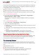
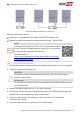
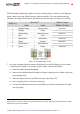
Table Of Contents
- Disclaimers
- Revision History
- HANDLING AND SAFETY INSTRUCTIONS
- IMPORTANT SAFETY INSTRUCTIONS
- Chapter 1: Overview
- Chapter 2: Installing the Power Optimizer
- Chapter 3: Installing the Inverter
- Chapter 4: Installing the Battery
- Chapter 5: Connecting the Inverter
- Chapter 6: Activating, Commissioning and Configuring the System
- Chapter 7: Setting Up Communication to the Monitoring Platform
- Appendix A: Errors and Troubleshooting
- Appendix B: Mechanical Specifications
- Appendix C: Replacing and Adding System Components
- Appendix D: Powering the LG Chem Battery Off and On
- Single Phase Energy Hub Inverter with Prism Technology - Technical Specificat...
- Support Contact Information

Pinpoint the location of alerted components using the physical layout.
The monitoring platform enables accessing site information, including up-to-date
information viewed in a physical or logical view:
Logical Layout: Shows a schematic tree-layout of the components in the system,
such as: inverters, strings, panels, meters and sensors, as well as their electrical
connectivity. This view enables you to see which panels are connected in each
string, which strings are connected to each inverter, and so on.
Physical Layout: Provides a bird's eye view of the actual placement of panels in the
site, and allows pinpoint issues to the exact location of each panel on a virtual site
map.
If you do not report the mapping of the installed power optimizers, the monitoring
platform will show the logical layout indicating which power optimizers are connected
to which inverter, but will not show strings or the physical location of power optimizers.
The monitoring platform includes a built-in help system, that guides you
through the monitoring functionality.
For more information, refer to https://www.solaredge.com/products/pv-
monitoring#/.
Creating Logical and Physical Layout using
Installation Information
To display a logical layout, insert the inverter serial number in the new site created in
the monitoring platform. When the communication between the inverter and the
monitoring server is established, the logical layout is displayed.
To display a physical layout, you need to map the locations of the installed power
optimizers. To map the locations, use one of the methods described in the next sections.
Designer
Designer recommends inverter and power optimizer selection per site size and enables
report generation. You can create a project in Designer and export the site design with
the string layout to the monitoring platform.
For more information, refer to
https://www.solaredge.com/products/installer-tools/designer#/.
Mapper Application
Use the Mapper smart phone application to scan the power optimizer
and inverter 2D bar-codes and create a virtual map of a PV site for
enhanced monitoring and easier maintenance.
Single Phase Energy Hub Inverter with Prism Technology MAN-01-00671-1.3
52 Designer