
Installation Manual

3.
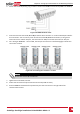
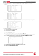
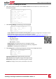
Insertthecardintothecommunicationboardslotmarked“CARD”.
Figure 42: Inserting the upgrade card
4. TurnONthebatteryAUXswitchandcircuitbreaker.Wait1minutebeforeproceeding.
5.
TurnONACtotheinverter.
WARNING!
ELECTRICAL SHOCK HAZARD. Do not touch uninsulated wires when the inverter cover is
removed.
RISQUE D’ÉLECTROCUTION, ne touchez pas les fils non isolés lorsque le couvercle de l'onduleur
est retiré.
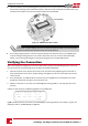
6. Theupgradestartsautomatically.WaitforthemessageDonetobedisplayedontheLCD.
7. Removethecardfromtheinverter.
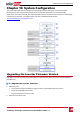
Configuring the RS485 Bus for Battery and Meter
Connection
ThissectiondescribeshowtosetuptheRS485communicationbetweentheinverter,
meterandonebattery.
Forinformationonconfiguringtwobatteries,refertotheStorEdgeApplications
ConnectionandConfigurationGuideavailableat
http://www.solaredge.com/sites/default/files/storedge_applications_connection_and_
configuration_guide_na.pdf.
Someinvertersareequippedwithabuilt-inRevenueGradeMeter(RGM),whichislocatedinthe
ConnectionUnit.Whenanadditionalmeterisinstalledfortheseinverters,thesecondmeteris
connectedtotheexistingRGMinadaisychain.
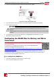
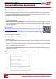
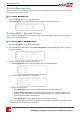
To configure the RS485 bus:
1. TurnOFForverifythattheConnectionUnitswitchisOFF.
2. TurntheinverterON/OFFswitchtoOFF.
SolarEdge-StorEdge Installation Guide MAN-01-00262-1.3
82
Configuring the RS485 Bus for Battery and Meter Connection