
Installation Manual

10.
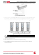
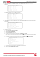
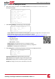
TerminatethefirstandlastSolarEdgedevice(inverter/ControlandCommunicationgateway,etc.)in
thechainbyswitchingaterminationDIP-switchinsidetheinvertertoON(movetheleftswitchup).
TheswitchislocatedonthecommunicationboardandismarkedSW7.
Figure 41: RS485 termination switch
NOTE
Only the first and last SolarEdge devices in the chain should be terminated. The other inverters in
the chain should have the termination switch OFF (down position).
11. Ifnotusingsurgeprotection,connectthegroundingwiretothefirstinverterintheRS485chain;
makesurethegroundingwireisnotincontactwithotherwires.ForinverterswithaDCSafety
Switch,connectthegroundingwiretothegroundingbus-barintheDCSafetySwitch.
Verifying the Connection
Afterconnectingandconfiguringacommunicationoption,performthefollowingstepstocheckthat
theconnectiontothemonitoringserverhasbeensuccessfullyestablished.
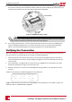
1. Closetheinvertercover:Attachtheinvertercoverandsecureitbytighteningthescrewswitha
torqueof9.0N*m/6.6lb.*ft.Forpropersealing,firsttightenthecornerscrewsandthenthetwo
centralscrews.
2. IfnotalreadyON-TurnONtheACtotheinverterbyturningONthecircuitbreakeronthemain
distributionpanelandturningontheConnectionUnit.
3. WaitfortheinvertertoconnecttotheSolarEdgemonitoringplatform.Thismaytakeuptotwo
minutes.
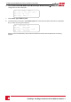
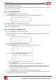
AstatusscreensimilartothefollowingappearsontheLCDpanel:
V a c [ V ] V d c [ V ] P a c [ w ]
2 4 0 . 7 1 4 . 1 0 . 0
P _ O K : 0 0 0 / 0 0 0 < S _ O K >
- - - - - - - - - - - - - - - O F F
S_OK:IndicatesthattheconnectiontotheSolarEdgemonitoringplatformissuccessful.IfS_OKisnot
displayed,referto"Troubleshooting"onpage93.
SolarEdge-StorEdge Installation Guide MAN-01-00262-1.3
80
Verifying the Connection