
Installation Guide
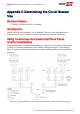
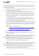
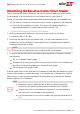
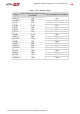


Table Of Contents
- Disclaimers
- Support and Contact Information
- Revision History
- Contents
- HANDLING AND SAFETY INSTRUCTIONS
- IMPORTANT SAFETY INSTRUCTIONS
- Chapter 1: Introducing the SolarEdge Power Harvesting System
- Chapter 2: Installing the Power Optimizers
- Chapter 3: Installing the Inverter
- Chapter 4: Connecting the AC and the Strings to the Safety Switch
- Chapter 5: Commissioning the Installation
- Chapter 6: User Interface
- Chapter 7: Setting Up Communication
- Appendix A: Errors and Troubleshooting
- Appendix B: Mechanical Specifications
- Appendix C: External Fan Maintenance and Replacement
- Appendix D: Replacing and Adding System Components
- Appendix E: Determining the Circuit Breaker Size
- Technical Specifications - Single Phase Inverters (North America)
- Technical Specifications - Three Phase Inverters (North America)
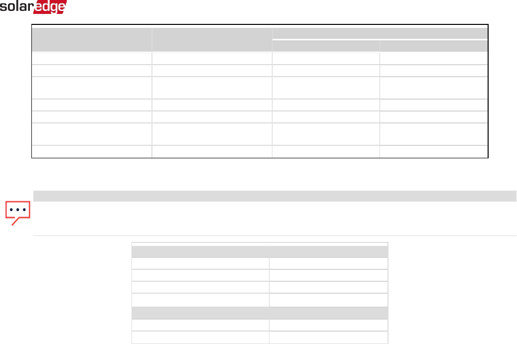
Inverter
Maximum Output Current
(A)
Maximum Suggested Fuse Rating (A)
208 VAC 240 VAC
SE3000A-US 12.5 --- 20
SE3800A-US 16 --- 20
SE5000A-US
24 @208V
21 @240V
30 30
SE6000A-US 25 --- 35 or 40
SE7600-US 32 --- 40
SE10000-US
48 @ 208V
42@ 240V
60 60
SE11400-US 47.5 --- 60
Default Trip Limits and Times According to IEEE1547
NOTE
The inverters are equipped with adjustable utility protective function set-points, and can be aggregated above 30kW on a
single Point of Common Connection. The default settings are in compliance with IEEE1547. Utility authorization is required
to change these set-points.
Voltage Range (% of Base Voltage) Maximum Clearing Time (Sec)
V < 50% 0.16
50 % < V < 88% 2.00
110% < V < 120% 1.00
V > 120 % 0.16
Frequency Range (Hz) Maximum Clearing Time (Sec)
> 60.5 0.16
< 59.3 (Hawaii – 57) 0.16
SolarEdge-Three Phase System Installation Guide MAN-01-00002-4.3
119