
Installation Guide
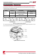
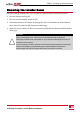
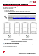
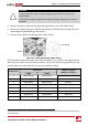
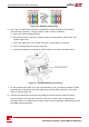
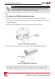
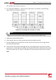

Figure 36: Standard cable wiring
6. Useapre-crimpedcabletoconnectviagland#1totheRJ45plugontheinverter's
communicationboardor,ifusingaspoolofcable,connectasfollows:
a. Insertthecablethroughgland#1.
b. Removethecable’sexternalinsulationusingacrimpingtoolorcablecutterand
exposeeightwires.
c. InserttheeightwiresintoanRJ45connector,asdescribedinFigure 36
d. Useacrimpingtooltocrimptheconnector.
e. ConnecttheEthernetconnectortotheRJ45portonthecommunicationboard.
Figure 37: The RJ45 Ethernet connection
7. Fortheswitch/routerside,useapre-crimpedcableoruseacrimpertoprepareanRJ45
communicationconnector:InserttheeightwiresintotheRJ45connectorinthesame
orderasabove(Figure 36).
8. ConnectthecableRJ45connectortotheRJ45portoftheEthernetswitchorrouter.
Youcanconnectmorethanoneinvertertothesameswitch/routerortodifferent
switches/routers,asneeded.Eachinvertersendsitsmonitoreddataindependentlytothe
SolarEdgemonitoringportal.
SolarEdge-Installation Guide MAN-01-00002-4.0
76
Creating an Ethernet (LAN) Connection