
Install Manual
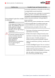
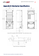
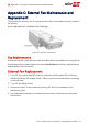
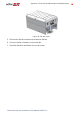
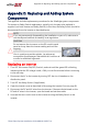
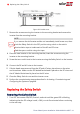
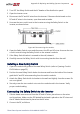
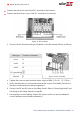
Table Of Contents
- Disclaimers
- Revision History
- Contents
- HANDLING AND SAFETY INSTRUCTIONS
- IMPORTANT SAFETY INSTRUCTIONS
- Chapter 1: Introducing the SolarEdge Power Harvesting System
- Chapter 2: Installing the Power Optimizer
- Chapter 3: Installing the Inverter
- Chapter 4: Connecting the AC and the Strings to the Safety Switch
- Chapter 5: Activating, Commissioning and Configuring the System
- Chapter 6: Setting Up Communication to the Monitoring Platform
- Appendix A: Errors and Troubleshooting
- Appendix B: Mechanical Specifications
- Appendix C: External Fan Maintenance and Replacement
- Appendix D: Replacing and Adding System Components
- Determining the Circuit Breaker Size
- Support Contact Information

Connect the red wire to any of the DC+ terminals in the inverter.
Connect the black wire to any of the DC- terminals in the inverter.
Figure 41: DC terminals
3.
Connect the AC wires according to the labels on the ACterminal blocks, as follows:
Wire type Connect to terminal
Figure 42: AC terminals
Line 1 L1
Line 2 L2
Line 3 L3
PE (grounding)
Neutral N
4. Tighten the screws of each terminal with a torque of 0.88-1.1 lb.*ft / 1.2-1.5 N*m.
5. Verify that there are no unconnected wires at the output of the Safety Switch and
that any unused terminal screws are tightened.
6. Connect the DC and AC wires to the Safety Switch. Refer to
Connecting the AC and
the Strings to the Safety Switch
on page 38.
7. Ensure proper conduit sealing; inspect the entire conduit run and use standard
conduit sealants to avoid water penetration.
Three Phase System Installation Guide MAN-01-00527-1.4
78 Replacing the Safety Switch