
Install Manual
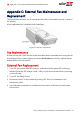
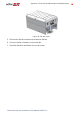
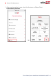
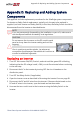
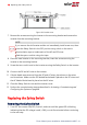
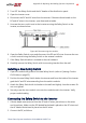
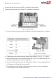
Table Of Contents
- Disclaimers
- Revision History
- Contents
- HANDLING AND SAFETY INSTRUCTIONS
- IMPORTANT SAFETY INSTRUCTIONS
- Chapter 1: Introducing the SolarEdge Power Harvesting System
- Chapter 2: Installing the Power Optimizer
- Chapter 3: Installing the Inverter
- Chapter 4: Connecting the AC and the Strings to the Safety Switch
- Chapter 5: Activating, Commissioning and Configuring the System
- Chapter 6: Setting Up Communication to the Monitoring Platform
- Appendix A: Errors and Troubleshooting
- Appendix B: Mechanical Specifications
- Appendix C: External Fan Maintenance and Replacement
- Appendix D: Replacing and Adding System Components
- Determining the Circuit Breaker Size
- Support Contact Information

2. Turn OFF the Safety Switch and the AC breaker of the distribution panel.
3. Open the inverter cover.
4. Disconnect the DC and AC wires from the inverter. If there are ferrite beads on the
DC and AC wires in the inverter, open them and set aside.
5.
Unscrew the two conduit nuts in the inverter securing the Safety Switch to the
inverter, as shown below:
Figure 40: Disconnecting the conduits
6. Open the Safety Switch cover and disconnect the DC and AC wires. Unscrew the two
conduit nuts securing the Safety Switch to the external conduits.
7. If the Safety Switch bracket is screwed to the wall, release it.
8. Carefully remove the Safety Switch with its mounting bracket from the wall.
Installing a New Safety Switch
1. Open the conduit drill guides of the new Safety Switch (refer to
Opening Conduit
Drill Guides
on page 33).
2. Position the new Safety Switch below the inverter and from the inside of the inverter
grab the AC and DC wires extending from the switch conduits.
3. Attach the Safety Switch with its bracket to the wall and slightly close the screws. Do
not over tighten.
4. Securely screw the two conduit nuts onto the conduit ends in the inverter. Verify
proper conduit sealing.
Connecting the Safety Switch to the Inverter
1. If ferrite beads were removed from the DC and AC wires, place them on the wires
and close them. Make sure the DC labeled ferrite bead is placed on the DC wires and
the AC labeled ferrite bead is placed on the AC wires.
2. Connect the DC, as follows:
Appendix D: Replacing and Adding System Components 77
Three Phase System Installation Guide MAN-01-00527-1.4