
Install Manual
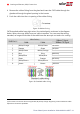
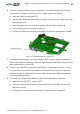
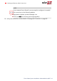

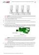

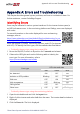

Table Of Contents
- Disclaimers
- Revision History
- Contents
- HANDLING AND SAFETY INSTRUCTIONS
- IMPORTANT SAFETY INSTRUCTIONS
- Chapter 1: Introducing the SolarEdge Power Harvesting System
- Chapter 2: Installing the Power Optimizer
- Chapter 3: Installing the Inverter
- Chapter 4: Connecting the AC and the Strings to the Safety Switch
- Chapter 5: Activating, Commissioning and Configuring the System
- Chapter 6: Setting Up Communication to the Monitoring Platform
- Appendix A: Errors and Troubleshooting
- Appendix B: Mechanical Specifications
- Appendix C: External Fan Maintenance and Replacement
- Appendix D: Replacing and Adding System Components
- Determining the Circuit Breaker Size
- Support Contact Information

NOTE
Do not cross-connect B, A and G wires.
7. Tighten the terminal block screws.
8. Check that the wires are fully inserted and cannot be pulled out easily.
9.
Push the RS485 terminal block firmly all the way into the connector on the right side
of the communication board.
10.
Terminate the first and last SolarEdge device in the chain by switching a termination
DIP-switch inside the inverter to ON (move the left switch up). The switch is located
on the communication board and is marked SW7SW1.
Figure 34: RS485 termination switch
NOTE
Only the first and last SolarEdge devices in the chain should be terminated.
The other inverters in the chain should have the termination switch OFF
(down position).
11. If not using surge protection, connect the grounding wire to the first inverter in the
RS485 chain; make sure the grounding wire is not in contact with other wires. For
inverters with a Safety Switch, connect the grounding wire to the grounding bus-
bar in the Safety Switch.
Chapter 6: Setting Up Communication to the Monitoring Platform 65
Three Phase System Installation Guide MAN-01-00527-1.4