
Install Manual
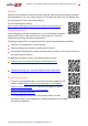
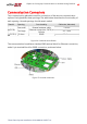
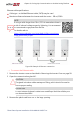
Table Of Contents
- Disclaimers
- Revision History
- Contents
- HANDLING AND SAFETY INSTRUCTIONS
- IMPORTANT SAFETY INSTRUCTIONS
- Chapter 1: Introducing the SolarEdge Power Harvesting System
- Chapter 2: Installing the Power Optimizer
- Chapter 3: Installing the Inverter
- Chapter 4: Connecting the AC and the Strings to the Safety Switch
- Chapter 5: Activating, Commissioning and Configuring the System
- Chapter 6: Setting Up Communication to the Monitoring Platform
- Appendix A: Errors and Troubleshooting
- Appendix B: Mechanical Specifications
- Appendix C: External Fan Maintenance and Replacement
- Appendix D: Replacing and Adding System Components
- Determining the Circuit Breaker Size
- Support Contact Information

Ethernet cable specifications:
Cable type – a shielded Ethernet cable (CAT6) may be used
Maximum distance between the inverter and the router – 100 m/ 330 ft.
NOTE
If using a cable longer than 10 m / 33 ft in areas where there is
a risk of induced voltage surges by lightning, it is recommend
to use external surge protection devices.
For details refer to:
https://www.solaredge.com/sites/default/files/overvoltage_
surge_protection_na.pdf.
Figure 28: Example of Ethernet connection
To connect the Ethernet cable:
1. Remove the inverter cover as described in
Removing the Inverter Cover
on page 58.
2.
Open the communication gland #1.
CAUTION!
The gland includes a rubber waterproof fitting, which should be used to
ensure proper sealing.
ATTENTION!
Le cote interne du gland contient une rondelle qui doit être utilisée pour
une bonne étancheïté.
3. Remove the plastic seal from one of the large opening .
Chapter 6: Setting Up Communication to the Monitoring Platform 59
Three Phase System Installation Guide MAN-01-00527-1.4