
Install Manual
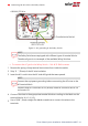
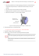
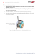
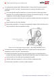
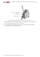
Table Of Contents
- Disclaimers
- Revision History
- Contents
- HANDLING AND SAFETY INSTRUCTIONS
- IMPORTANT SAFETY INSTRUCTIONS
- Chapter 1: Introducing the SolarEdge Power Harvesting System
- Chapter 2: Installing the Power Optimizer
- Chapter 3: Installing the Inverter
- Chapter 4: Connecting the AC and the Strings to the Safety Switch
- Chapter 5: Activating, Commissioning and Configuring the System
- Chapter 6: Setting Up Communication to the Monitoring Platform
- Appendix A: Errors and Troubleshooting
- Appendix B: Mechanical Specifications
- Appendix C: External Fan Maintenance and Replacement
- Appendix D: Replacing and Adding System Components
- Determining the Circuit Breaker Size
- Support Contact Information

wire fuse holder of the inverter, and in the 3-wire fuse holder there is a plastic dummy
fuse.
To set the inverter for 3-wire grid connection, you must move the fuse from the 4-wire
fuse holder, marked as Y GRID, to the 3-wire fuse holder, marked as ∆ GRID (see
Figure
20
).
To set the inverter for 208V 3-wire grid connection:
NOTE
This procedure is relevant for the following inverter models:
3 phase commercial inverter, part numbers SEXXK-XXXXXBXX4
3 phase inverters with Synergy technology, part numbers SEXXXK-
XXXP0BXX4.
This procedure is
not
relevant for inverters with the following part numbers:
SEXXXK-XXXXIBXX4
NOTE
Perform this procedure for
all
inverter units, before connecting them to the AC
Grid.
1. Remove the inverter cover: Open the inverter cover’s six Allen screws and carefully
pull the cover horizontally before lowering it.
2.
Identify the fuse locations and the markings as described in
Figure 20
.
Figure 20: Fuse locations and markings
3. Remove the dummy fuse from the 3-wire grid fuse holder and set it aside.
4. Move the fuse from the 4-wire grid fuse holder to the 3-wire grid fuse holder.
5. Place the dummy fuse in the 4-wire grid fuse holder.
6. During system setup, set the country to the appropriate 3-wire grid option. Using
the non-3-wire setting may result in incorrect system operation.
Three Phase System Installation Guide MAN-01-00527-1.4
40 Setting the Inverter to Support 208V 3-Wire Grid