
Install Manual
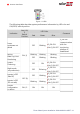
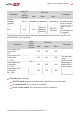
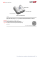
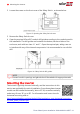
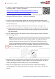
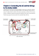
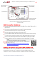
Table Of Contents
- Disclaimers
- Revision History
- Contents
- HANDLING AND SAFETY INSTRUCTIONS
- IMPORTANT SAFETY INSTRUCTIONS
- Chapter 1: Introducing the SolarEdge Power Harvesting System
- Chapter 2: Installing the Power Optimizer
- Chapter 3: Installing the Inverter
- Chapter 4: Connecting the AC and the Strings to the Safety Switch
- Chapter 5: Activating, Commissioning and Configuring the System
- Chapter 6: Setting Up Communication to the Monitoring Platform
- Appendix A: Errors and Troubleshooting
- Appendix B: Mechanical Specifications
- Appendix C: External Fan Maintenance and Replacement
- Appendix D: Replacing and Adding System Components
- Determining the Circuit Breaker Size
- Support Contact Information

Figure 19: Inside the Safety Switch for three phase inverters
(14.4kW & 33.3kW)
Grid Connection Guidelines
Equipment grounding tightening torques: 4-6 AWG: 45 lb-in, 8 AWG: 40 lb-in, 10-14
AWG: 35 lb-in.
The conduits, hubs and fittings must be suited for field wiring systems.
The hubs and other fittings must comply with UL514B.
Use only copper conductors rated for a minimum of 90°C.
For the SE10KUS, SE20KUS, SE33.3KUS three phase inverters where opposite polarity
DC conductors are routed in the same conduit, 1000V rated cables must be used.
Use the conduit and wiring appropriate for the installation location per the NEC.
Outdoor installations must use components that are rated NEMA 3R or higher.
NOTE
For more wiring information refer to the
SolarEdge
Recommended AC Wiring Application Note
, available on the
SolarEdge website at
https://www.solaredge.com/sites/default/files/application-
note-recommended-wiring.pdf
Setting the Inverter to Support 208V 3-Wire Grid
SolarEdge inverters that support the 208V 3-wire grid are equipped with two fuse
holders and a fuse in each unit. The position of the fuse configures the AC grid
connection: 4-wire or 3-wire grid connection. By default, the fuse is located in the 4-
Chapter 4: Connecting the AC and the Strings to the Safety Switch 39
Three Phase System Installation Guide MAN-01-00527-1.4