
Install Manual
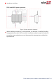
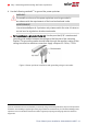
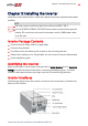
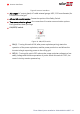
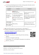
Table Of Contents
- Disclaimers
- Revision History
- Contents
- HANDLING AND SAFETY INSTRUCTIONS
- IMPORTANT SAFETY INSTRUCTIONS
- Chapter 1: Introducing the SolarEdge Power Harvesting System
- Chapter 2: Installing the Power Optimizer
- Chapter 3: Installing the Inverter
- Chapter 4: Connecting the AC and the Strings to the Safety Switch
- Chapter 5: Activating, Commissioning and Configuring the System
- Chapter 6: Setting Up Communication to the Monitoring Platform
- Appendix A: Errors and Troubleshooting
- Appendix B: Mechanical Specifications
- Appendix C: External Fan Maintenance and Replacement
- Appendix D: Replacing and Adding System Components
- Determining the Circuit Breaker Size
- Support Contact Information

Figure 9: Inverter Interfaces
ACoutput: ACoutput gland, AC cable external gauge, M32 (15-21mm diameter) for
connection to the grid
AC and DC conduit entries: Connection points of the Safety Switch.
Two communication glands: for connection of inverter communication options.
Each gland has three openings.
ON/OFF/P switch:
Figure 10: ON/OFF/P switch
ON (1) - Turning this switch ON (after power optimizer pairing) starts the
operation of the power optimizers, enables power production and allows the
inverter to begin exporting power to the utility grid.
OFF (0) - Turning this switch OFF reduces the power optimizer voltage to a low
safety voltage and inhibits exportation of power. When this switch is OFF, the
control circuitry remains powered up.
Three Phase System Installation Guide MAN-01-00527-1.4
28 Inverter Interfaces