
Install Manual
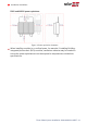
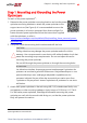
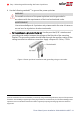
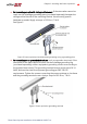
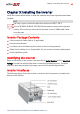
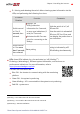
Table Of Contents
- Disclaimers
- Revision History
- Contents
- HANDLING AND SAFETY INSTRUCTIONS
- IMPORTANT SAFETY INSTRUCTIONS
- Chapter 1: Introducing the SolarEdge Power Harvesting System
- Chapter 2: Installing the Power Optimizer
- Chapter 3: Installing the Inverter
- Chapter 4: Connecting the AC and the Strings to the Safety Switch
- Chapter 5: Activating, Commissioning and Configuring the System
- Chapter 6: Setting Up Communication to the Monitoring Platform
- Appendix A: Errors and Troubleshooting
- Appendix B: Mechanical Specifications
- Appendix C: External Fan Maintenance and Replacement
- Appendix D: Replacing and Adding System Components
- Determining the Circuit Breaker Size
- Support Contact Information

Chapter 3: Installing the Inverter
Install the inverter either before or after the modules and power optimizers have been
installed.
NOTE
Use only copper conductors rated for a minimum of 90°C/ 194°F.
For the SE10KUS, SE20KUS, SE33.3KUS three phase inverters where opposite
polarity DC conductors are routed in the same conduit, 1000V rated cables
must be used.
Inverter Package Contents
One inverter with Safety Switch (if applicable)
One mounting bracket
Two Allen screws for fastening the inverter to the mounting bracket
Safety Switch sealing cover (if applicable, for use in case of inverter replacement)
Quick Installation guide
Identifying the Inverter
Refer to the sticker on the inverter that specifies its Serial Number and its Electrical
Ratings. Provide the serial number when contacting SolarEdge support. The serial
number is also required when opening a new site in the monitoring platform.
Inverter Interfaces
The following figure shows the inverter connectors and components, located at the
bottom of the inverter.
Chapter 3: Installing the Inverter 27
Three Phase System Installation Guide MAN-01-00527-1.4