
Install Manual
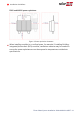
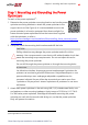
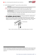
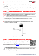
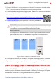
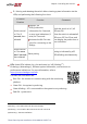
Table Of Contents
- Disclaimers
- Revision History
- Contents
- HANDLING AND SAFETY INSTRUCTIONS
- IMPORTANT SAFETY INSTRUCTIONS
- Chapter 1: Introducing the SolarEdge Power Harvesting System
- Chapter 2: Installing the Power Optimizer
- Chapter 3: Installing the Inverter
- Chapter 4: Connecting the AC and the Strings to the Safety Switch
- Chapter 5: Activating, Commissioning and Configuring the System
- Chapter 6: Setting Up Communication to the Monitoring Platform
- Appendix A: Errors and Troubleshooting
- Appendix B: Mechanical Specifications
- Appendix C: External Fan Maintenance and Replacement
- Appendix D: Replacing and Adding System Components
- Determining the Circuit Breaker Size
- Support Contact Information

1. Connect the Minus (-) output connector of the string’s first power optimizer to the
Plus (+) output connector of the string’s second power optimizer.
2.
To minimize electromagnetic interference (EMI), make sure to minimize the distance
between the positive and negative DC cables.
For detailed instructions, see:
https://www.solaredge.com/sites/default/files/se-emi-performance-
application-note.pdf.
3.
Connect the rest of the power optimizers in the string in the same
manner.
WARNING!
If using a dual-input power optimizer and some inputs are not used, seal the
unused input connectors with the supplied pair of seals.
AVERTISSEMENT!
Si un optimiseur à double entrées est utilisé et que certaines entrées ne sont
pas connectées, fermez ces entrées avec la paire de couvercles fournie.
Figure 8: Power optimizers connected in series
4.
If you intend to monitor the installation, using the monitoring platform, record the
physical location of each power optimizer, as described in
Creating Logical and
Physical Layout using Installation Information
on page 52.
Step 4: Verifying Proper Power Optimizer Connection
When a module is connected to a power optimizer, the power optimizer outputs a safe
voltage of 1V (±0.1V). Therefore, the total string voltage should equal 1V times the
number of power optimizers connected in series in the string. For example, if 10 power
optimizers are connected in a string, then 10V should be produced.
Chapter 2: Installing the Power Optimizer 25
Three Phase System Installation Guide MAN-01-00527-1.4