
Install Manual
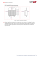
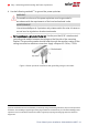
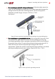
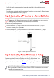
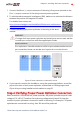
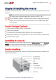
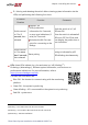
Table Of Contents
- Disclaimers
- Revision History
- Contents
- HANDLING AND SAFETY INSTRUCTIONS
- IMPORTANT SAFETY INSTRUCTIONS
- Chapter 1: Introducing the SolarEdge Power Harvesting System
- Chapter 2: Installing the Power Optimizer
- Chapter 3: Installing the Inverter
- Chapter 4: Connecting the AC and the Strings to the Safety Switch
- Chapter 5: Activating, Commissioning and Configuring the System
- Chapter 6: Setting Up Communication to the Monitoring Platform
- Appendix A: Errors and Troubleshooting
- Appendix B: Mechanical Specifications
- Appendix C: External Fan Maintenance and Replacement
- Appendix D: Replacing and Adding System Components
- Determining the Circuit Breaker Size
- Support Contact Information

5. Verify that each power optimizer is securely attached to the module support
structure.
6. Record power optimizer serial numbers and locations, as described in
Reporting and
Monitoring Installation Data
on page 51.
Step 2: Connecting a PV module to a Power Optimizer
NOTE
Images are for illustration purposes only. Refer to the label on the product to
identify the plus and minus input and output connectors.
For each of the power optimizers:
Connect the Plus (+) output connector of the module to the Plus (+) input
connector of the power optimizer.
Connect the Minus (-) output connector of the module to the Minus (-) input
connector of the power optimizer.
Figure 7: Power optimizer connectors
Step 3: Connecting Power Optimizers in Strings
You can construct parallel strings of unequal length, that is, the number
of power optimizers in each string does not have to be the same. The
minimum and maximum string lengths are specified in the power
optimizer datasheets. Refer to the Designer for string length verification.
IMPORTANTSAFETYFEATURE
For a compliant PVRapid Shutdown System (PVRSS) installation, use no more
than 30 optimizers per string.
Three Phase System Installation Guide MAN-01-00527-1.4
24 Step 2: Connecting a PV module to a Power Optimizer