
Install Manual
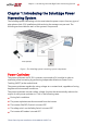
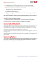
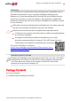
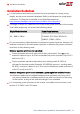
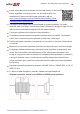
Table Of Contents
- Disclaimers
- Revision History
- Contents
- HANDLING AND SAFETY INSTRUCTIONS
- IMPORTANT SAFETY INSTRUCTIONS
- Chapter 1: Introducing the SolarEdge Power Harvesting System
- Chapter 2: Installing the Power Optimizer
- Chapter 3: Installing the Inverter
- Chapter 4: Connecting the AC and the Strings to the Safety Switch
- Chapter 5: Activating, Commissioning and Configuring the System
- Chapter 6: Setting Up Communication to the Monitoring Platform
- Appendix A: Errors and Troubleshooting
- Appendix B: Mechanical Specifications
- Appendix C: External Fan Maintenance and Replacement
- Appendix D: Replacing and Adding System Components
- Determining the Circuit Breaker Size
- Support Contact Information

Installation Guidelines
For the minimum and maximum number of power optimizers in a string (string
length), see the power optimizer datasheets. Refer to the Designer for string length
verification. The Designer is available on the SolarEdge website at:
https://www.solaredge.com/us/products/installer-tools/designer#/.
The length of home-run cables from the first and last power optimizer to the inverter
(total cable length) may not exceed the following values:
Single Phase Inverters Three Phase Inverters
All - 1000 ft. /300 m
SE9KUS, SE20KUS - 1000 ft. /300 m
SE14.4KUS, SE17.3KUS, SE33.3KUS,
SE40KUS - 2300 ft. /700 m
Do not
use extension cables between a module and a power optimizer, between two
modules connected to the same power optimizer, or between two power optimizers
other than in the following cases:
Between a power optimizer and a module:
Power optimizers with the 4-type suffix in their part number (Pxxx-4xxxxxx) -
extension cables of up to 16 m can be installed per power optimizer (8 m for DC+
and 8 m for DC-).
Power optimizers manufactured starting from working week 42, 2019, as
indicated in the serial number (Example:S/N SJ5019A-xxxxxxxx - working week
50, 2019) - extension cables of up to 16 m can be installed per power optimizer (8
m for DC+ and 8 m for DC-).
Between two power optimizers or between a power optimizer and the inverter:
Extension cables can be installed between power optimizers only from row to
row, around obstacles or pathways within a row, and from the end of the string
to the inverter, as long as the total cable length is not exceeded.
For connecting power optimizers to the inverter, use cables with a minimum cross-
section of 11 AWG/ 4 mm² DC cables.
Three Phase System Installation Guide MAN-01-00527-1.4
18 Installation Guidelines