Installation Guide Three Phase System with SetApp Configuration For North America Version 1.
Disclaimers Disclaimers Important Notice Copyright © SolarEdge Inc. All rights reserved. No part of this document may be reproduced, stored in a retrieval system or transmitted, in any form or by any means, electronic, mechanical, photographic, magnetic or otherwise, without the prior written permission of SolarEdge Inc. The material furnished in this document is believed to be accurate and reliable. However, SolarEdge assumes no responsibility for the use of this material.
2 FCC Compliance FCC Compliance This equipment has been tested and found to comply with the limits for a Class B digital device, pursuant to part 15 of the FCC Rules. These limits are designed to provide reasonable protection against harmful interference in a residential installation. This equipment generates, uses and can radiate radio frequency energy and, if not installed and used in accordance with the instructions, may cause harmful interference to radio communications.
Revision History Revision History Version 1.4 (August 2020) Updated the communication board TCP details in Creating an Ethernet (LAN) Connection on page 58. Changed the cable type required for the RS485 and Ethernet connection to CAT6. Added the requirement for a special bracket, when installing close to the shoreline in Mounting the Inverter on page 34. For inverter clearance, added a link to Application Note - Clearance Guidelines in Mounting the Inverter on page 34.
4 Contents Contents Disclaimers Important Notice FCC Compliance 1 1 2 Revision History 3 Contents 4 HANDLING AND SAFETY INSTRUCTIONS Safety Symbols Information 6 6 IMPORTANT SAFETY INSTRUCTIONS 7 Chapter 1: Introducing the SolarEdge Power Harvesting System Power Optimizer Inverter with Safety Switch Monitoring Platform Supported AC Grids Installation Procedure Installation Equipment List Inverter Transport and Storage 11 11 12 12 13 13 13 14 Chapter 2: Installing the Power Optimizer Safety Pack
Contents 5 Step 2: Commissioning and Configuring the Installation Step 3: Verifying Proper Activation and Commissioning Reporting and Monitoring Installation Data Designer Mapper Application Physical Layout Editor Using a Paper Template 49 51 51 53 53 53 54 Chapter 6: Setting Up Communication to the Monitoring Platform Communication Options Communication Connectors Removing the Inverter Cover Removing the DC Safety Unit Cover (if applicable) Creating an Ethernet (LAN) Connection Creating an RS485 Bus Co
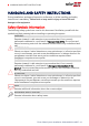
6 HANDLING AND SAFETY INSTRUCTIONS HANDLING AND SAFETY INSTRUCTIONS During installation, testing and inspection, adherence to all the handling and safety instructions is mandatory. Failure to do so may result in injury or loss of life and damage to the equipment. Safety Symbols Information The following safety symbols are used in this document. Familiarize yourself with the symbols and their meaning before installing or operating the system. WARNING! Denotes a hazard.
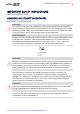
IMPORTANT SAFETY INSTRUCTIONS 7 IMPORTANT SAFETY INSTRUCTIONS SAVE THESE INSTRUCTIONS CONSIGNES DE SÉCURITÉ IMPORTANTES CONSERVEZ CES INSTRUCTIONS WARNING! The inverter cover must be opened only after switching the inverter ON/OFF/P switch located at the bottom of the inverter to OFF. This disables the DC voltage inside the inverter. Wait five minutes before opening the cover. Otherwise, there is a risk of electric shock from energy stored in the capacitors.
8 IMPORTANT SAFETY INSTRUCTIONS WARNING! The Safety Switch meets all requirements for a code-compliant installation of this system. The DC Disconnect Switch disconnects both the positive and negative conductors. AVERTISSEMENT! Le sectionneur externe (inclus) repond aux exigences de conformité pour l’installation de ce système . Le coupeur CC ouvre les conducteurs positifs et négatifs. WARNING! The inverter input and output circuits are isolated from the enclosure.
IMPORTANT SAFETY INSTRUCTIONS 9 WARNING! SolarEdge products can expose you to chemicals including antimony trioxide, which is known to the State of California to cause cancer. For more information, go to www.P65Warnings.ca.gov . AVERTISSEMENT! Les produits SolarEdge peut vous exposer à des agents chimiques, y compris trioxyde d'antimoine, identifiés par l'État de Californie comme pouvant causer le cancer. Pour de plus amples informations, prière de consulter www.P65Warnings.ca.gov.
10 IMPORTANT SAFETY INSTRUCTIONS NOTE A SolarEdge inverter may be installed in a site with a generator. SolarEdge requires installing a physical or electronic interlock, which will signal to the inverter when the grid has been disconnected. Interlock procurement, installation, maintenance and support are the responsibility of the installer.
Chapter 1: Introducing the SolarEdge Power Harvesting System 11 Chapter 1: Introducing the SolarEdge Power Harvesting System The SolarEdge power harvesting solution maximizes the power output from any type of solar photovoltaic (PV) installation while reducing the average cost per watt. The following sections describe each of the system’s components.
12 Inverter with Safety Switch The Rapid Shutdown (PVRSS) is initiated by one of the following methods: Inverter AC breaker is turned OFF, or AC to the inverter is disconnected by another method (intentionally or as result of a fault) Inverter ON/OFF/P switch is turned OFF The Safety Switch is turned OFF For inverters with Manual Rapid Shutdown, initiation is done by switching the Safety Switch OFF Each power optimizer also transmits module performance data over the DC power line to the inverter.
Chapter 1: Introducing the SolarEdge Power Harvesting System 13 Supported AC Grids Figure 2: AC grids supported by SolarEdge three phase inverters NOTE Grid support depends on the inverter model. Some three phase inverters support the 208V 3-wire grid. Refer to Setting the Inverter to Support 208V 3Wire Grid on page 39. Installation Procedure The following is the procedure for installing and setting up a new SolarEdge site. Many of these also apply to modification of an existing site. 1.
14 Inverter Transport and Storage Cordless drill (with a torque clutch) or screwdriver and bits suitable for the surface on which the inverter and optimizers will be installed and for opening the Safety Switch drill guides. Use of an impact driver is not allowed.
Chapter 2: Installing the Power Optimizer 15 Chapter 2: Installing the Power Optimizer Safety The following notes and warnings apply when installing the power optimizers. Some of the following may not be applicable to smart modules: WARNING! The metallic enclosure of the power optimizer must be grounded in accordance with the product's listing and local and national codes.
16 Safety CAUTION! All PV modules must be connected to a power optimizer. ATTENTION! Tous les modules doivent être connectés à un optimiseur de puissance. CAUTION! If you intend to mount the optimizers directly to the module or module frame, first consult the module manufacturer for guidance regarding the mounting location and the impact, if any, on module warranty. Drilling holes in the module frame should be done according to the module manufacturer instructions.
Chapter 2: Installing the Power Optimizer 17 ATTENTION! Les connecteurs du module doivent être mécaniquement compatibles avec les optimiseurs de puissance. Sinon, le système SolarEdge installé peut être dangereux ou causer des problèmes fonctionnels, tels que les défauts de terre, qui peuvent provoquer un arrêt de l’onduleur.
18 Installation Guidelines Installation Guidelines For the minimum and maximum number of power optimizers in a string (string length), see the power optimizer datasheets. Refer to the Designer for string length verification. The Designer is available on the SolarEdge website at: https://www.solaredge.com/us/products/installer-tools/designer#/.
Chapter 2: Installing the Power Optimizer 19 Frame-mounted power optimizers are mounted directly on the module frame, regardless of racking system (rail-less or with rails). For installation of frame-mounted power optimizers, refer to http://www.solaredge.com/sites/default/files/installing_frame_ mounted_power_optimizers.pdf. The steps in this chapter refer to module add-on power optimizers. For smart modules, start from Step 3: Connecting Power Optimizers in Strings on page 24.
20 Installation Guidelines P860 and M1600 power optimizers Figure 3: Power optimizer clearance When installing modules in a confined space, for example, if installing Buildingintegrated photovoltaic (BIPV) modules, ventilation measures may be needed to ensure the power optimizers are not be exposed to temperatures outside their specifications. Three Phase System Installation Guide MAN-01-00527-1.
Chapter 2: Installing the Power Optimizer 21 Step 1: Mounting and Grounding the Power Optimizers (1) For each of the power optimizers : 1. Determine the power optimizer mounting location and use the power optimizer mounting brackets to attach the power optimizer to the support structure (See Figure 4). It is recommended to mount the power optimizer in a location protected from direct sunlight.
22 Step 1: Mounting and Grounding the Power Optimizers (1) 4. Use the following methods to ground the power optimizer: WARNING! The metallic enclosure of the power optimizer must be grounded in accordance with the requirements of the local and national codes. AVERTISSEMENT! L'enceinte métallique de l’optimiseur de puissance doit être mise à la terre en accord avec les régulations locales et nationales.
Chapter 2: Installing the Power Optimizer For mounting on rails with sliding nut fasteners: If the star washer cannot be used, use the SolarEdge grounding plate (purchased separately) between the railing and the flat side of the mounting bracket. Use mounting specific hardware as needed. Apply a torque of 9.5 N*m / 7 lb*ft. See Figure 5.
24 Step 2: Connecting a PV module to a Power Optimizer 5. Verify that each power optimizer is securely attached to the module support structure. 6. Record power optimizer serial numbers and locations, as described in Reporting and Monitoring Installation Data on page 51. Step 2: Connecting a PV module to a Power Optimizer NOTE Images are for illustration purposes only. Refer to the label on the product to identify the plus and minus input and output connectors.
Chapter 2: Installing the Power Optimizer 25 1. Connect the Minus (-) output connector of the string’s first power optimizer to the Plus (+) output connector of the string’s second power optimizer. 2. To minimize electromagnetic interference (EMI), make sure to minimize the distance between the positive and negative DC cables. For detailed instructions, see: https://www.solaredge.com/sites/default/files/se-emi-performanceapplication-note.pdf. 3.
26 Step 4: Verifying Proper Power Optimizer Connection Make sure the PV modules are exposed to sunlight during this process. The power optimizer will only turn ON if the PV module provides at least 2W. In SolarEdge systems, due to the introduction of power optimizers between the PV modules and the inverter, the short circuit current ISC and the open circuit voltage VOC hold different meanings from those in traditional systems.
Chapter 3: Installing the Inverter Chapter 3: Installing the Inverter Install the inverter either before or after the modules and power optimizers have been installed. NOTE Use only copper conductors rated for a minimum of 90°C/ 194°F. For the SE10KUS, SE20KUS, SE33.3KUS three phase inverters where opposite polarity DC conductors are routed in the same conduit, 1000V rated cables must be used.
28 Inverter Interfaces Figure 9: Inverter Interfaces AC output: AC output gland, AC cable external gauge, M32 (15-21mm diameter) for connection to the grid AC and DC conduit entries: Connection points of the Safety Switch. Two communication glands: for connection of inverter communication options. Each gland has three openings.
Chapter 3: Installing the Inverter 29 P - Moving and releasing the switch allows viewing system information via the LEDs, and performing the following functions: P Position Duration Switch moved to P for 2 seconds, then released. Function Displays (via LEDs) production information for 5 seconds, or error type indications (if exist) for 5 seconds. Activates the Wi-Fi access point for connecting to the SetApp Switch moved to P for more Starts pairing than 5 seconds, then released.
30 Inverter Interfaces Figure 11: LEDs The following table describes system performance information by LED color and ON/OFF/P switch position.
Chapter 3: Installing the Inverter Indication ON/ OFF/ P Switch Position Inverter firmware upgrade Error 31 LED Color Comment Red ON / P Green Blue Alternating Alternating Any ON ON/ OFF/ Blinking/ Flickering Alternating ON/ OFF / Blinking The upgrade process can take up to 5 minutes Refer to Errors and Troubleshooting on page 67 The following table describes production percentage of AC information by LED color and ON/OFF/P switch position.
32 Inverter Interfaces Figure 12: DC Safety Unit NOTE When the Safety Switch is OFF (for example during maintenance) it may be locked to prevent a safety hazard: 1. Move the switch to the Lock position. 2. Insert the lock through the knob opening and lock. Three Phase System Installation Guide MAN-01-00527-1.
Chapter 3: Installing the Inverter 33 Opening Conduit Drill Guides This section describes how to open drill guides . CAUTION! SolarEdge does not permit opening or puncturing the Safety Switch in any location other than the pre-defined drill guide locations, or otherwise altering the construction of the enclosure, as this may compromise safety and will void the warranty. This includes, but is not limited to, the use of fasteners like rivets, screws, nails, inserts, or pins.
34 Mounting the Inverter 2. Loosen the screws on the front cover of the Safety Switch , as shown below: Figure 13: Opening the Safety Switch cover 3. Remove the Safety Switch cover. 4. Open the required AC and DC conduit drill guides according to the conduits used in the installation: The drill guides are located at the bottom, back and sides of the enclosure, each with two sizes: ¾'' and 1''. Open the required pair, taking care not to interfere with any of the internal components.
Chapter 3: Installing the Inverter 35 The inverter is supplied with a mounting bracket. Figure 15: Mounting bracket NOTE Make sure the mounting surface or structure can support the weight of the inverter and bracket, and make sure that it spans the width of the bracket. CAUTION! HEAVY OBJECT. To avoid muscle strain or back injury, use proper lifting techniques, and if required - a lifting aid. ATTENTION! Objet lourd.
36 Mounting the Inverter 2. To allow for proper heat dissipation, follow the guidelines specified in Application Note - Clearance Guidelines. https://www.solaredge.com/sites/default/files/se-clearanceguidelines-for-multiple-inverter-mounting.pdf Maintaining proper clearance between the inverter and other objects prevents power reduction due to excessive temperature. 3.
Chapter 3: Installing the Inverter 37 Figure 16: Hanging the inverter on the bracket 7. For inverters with Safety Switch - secure the Safety Switch bracket to the wall: Mark the location of the bracket screw for the Safety Switch and drill the hole. Fasten the bracket using a standard bolt. Verify that the bracket is firmly attached to the mounting surface. Figure 17: Safety Switch bracket 8.
38 Chapter 4: Connecting the AC and the Strings to the Safety Switch Chapter 4: Connecting the AC and the Strings to the Safety Switch The Safety Switch disconnects all ungrounded DC conductors in compliance with the National Electric Code (NEC; Specifically NEC690.35, which addresses ungrounded PV arrays). The Safety Switch is rated to the maximum operating conditions of the inverter. Inverters of different models are equipped with different sizes/ types of terminal blocks.
Chapter 4: Connecting the AC and the Strings to the Safety Switch 39 Figure 19: Inside the Safety Switch for three phase inverters (14.4kW & 33.3kW) Grid Connection Guidelines Equipment grounding tightening torques: 4-6 AWG: 45 lb-in, 8 AWG: 40 lb-in, 10-14 AWG: 35 lb-in. The conduits, hubs and fittings must be suited for field wiring systems. The hubs and other fittings must comply with UL514B. Use only copper conductors rated for a minimum of 90°C. For the SE10KUS, SE20KUS, SE33.
40 Setting the Inverter to Support 208V 3-Wire Grid wire fuse holder of the inverter, and in the 3-wire fuse holder there is a plastic dummy fuse. To set the inverter for 3-wire grid connection, you must move the fuse from the 4-wire fuse holder, marked as Y GRID, to the 3-wire fuse holder, marked as ∆ GRID (see Figure 20).
Chapter 4: Connecting the AC and the Strings to the Safety Switch 41 CAUTION! If the fuse was moved to support one of the grid types, do not connect the inverter to the other grid type without switching the fuse back to the correct holder. Connecting the inverter to grids when the fuse is incorrectly located may damage the inverter and void the warranty.
42 Connecting the AC Grid to the Safety Switch 4.0 N*M / 35 lb-in. Figure 21: AC grounding in the Safety Switch NOTE The Safety Switches are equipped with different types of terminal blocks. The above figure is one example of the available Safety Switches. To connect the AC grid to the Safety Switch – 14.4 & 33.3kW inverters: 1. Remove the spring-clamp terminal instructions from inside the switch. 2. Strip 1⅜ '' (35mm) of the AC wire insulation. 3.
Chapter 4: Connecting the AC and the Strings to the Safety Switch 43 1. Insert the screwdriver into the front opening and rotate it counterclockwise to activate the clamp mechanism. The side latch holds the clamp in the open position. 2. Insert the wire into the side opening as deep as possible. 3. Slightly rotate the screwdriver counter-clockwise to release the latch. 4. Remove the screwdriver – the wire is safely clamped. Figure 22: AC Spring-clamp terminal example - 33.3KW inverter 6.
44 Connecting the AC Grid to the Safety Switch 3. Connect the wires as follows: 1. Use a standard flat-blade screwdriver to connect the wires to the spring-clamp terminals (See Figure 23). 2. The screwdriver blade should fit freely in the terminal opening. Too large a blade can crack the plastic housing. 3. Insert the screwdriver, press the release mechanism and open the clamp. 4. Insert the wire into the round opening and remove the screwdriver – the wire is automatically clamped.
Chapter 4: Connecting the AC and the Strings to the Safety Switch 45 Connecting the Strings to the Safety Switch You can connect systems with multiple DC strings in parallel to the DC input terminals of the switch. Inverters have one, two or three pairs of DC input terminals, depending on the inverter power rating. If more strings are required, they can be connected in parallel using an external combiner box before connecting to the switch.
46 Connecting the Strings to the Safety Switch For three phase inverters 9kW, 10kW and 20kW - Connect the DC wires from the PV installation to the DC+ and DC- terminal blocks, according to the labels on the terminals: Use a standard flat-blade screwdriver to connect the wires to the spring-clamp terminals. The screwdriver blade should fit freely in the terminal opening. Too large a blade can crack the plastic housing.
Chapter 4: Connecting the AC and the Strings to the Safety Switch Figure 25: DC Spring-clamp terminal – 14.4kW and 33.3kW inverters 5. Close the Safety Switch cover: Attach the switch cover and secure it by tightening the four screws with a torque of 1.2 N*m / 0.9 ft.*lb. 6. Ensure proper conduit sealing; inspect the entire conduit run and use standard conduit sealants to avoid water penetration. Three Phase System Installation Guide MAN-01-00527-1.
48 Chapter 5: Activating, Commissioning and Configuring the System Chapter 5: Activating, Commissioning and Configuring the System You can connect communication options at this stage, as described in Setting Up Communication to the Monitoring Platform on page 55. After completing all connections, activate and commission the system using the inverter SetApp mobile application. You can download the SetApp from the Apple App Store and Google Play before arriving at the site.
Chapter 5: Activating, Commissioning and Configuring the System 49 3. When the activation is complete, do one of the following: Select Connect to Another Device to continue activating additional inverters. Select Start Commissioning for pairing and other system configuration. Step 2: Commissioning and Configuring the Installation This section describes how to use the SetApp menus for commissioning and configuring the inverter settings. Menus may vary in your application depending on your system type.
50 Step 2: Commissioning and Configuring the Installation Since the inverter is ON, the power optimizers start producing power and the inverter starts converting AC. WARNING! When you turn ON the inverter ON/OFF/P switch, the DC cables carry a high voltage and the power optimizers no longer output a safe output.
Chapter 5: Activating, Commissioning and Configuring the System 51 Power Control Power control options are detailed in the Power Control Application Note, available on the SolarEdge website at . The Grid Control option may be disabled. Enabling it opens additional options in the menu. The Energy Manager option is used for setting power export limitation, as described in the Export Limitation Application Note, available on the SolarEdge website at https://www.solaredge.
52 Reporting and Monitoring Installation Data The Monitoring Platform The monitoring platform provides enhanced PV performance monitoring and yield assurance through immediate fault detection and alerts at the module, string and system level. Using the platform, you can: View the latest performance of specific components. Find under-performing components, such as modules, by comparing their performance to that of other components of the same type.
Chapter 5: Activating, Commissioning and Configuring the System 53 Designer Designer recommends inverter and power optimizer selection per site size and enables report generation. You can create a project in Designer and export the site design with the string layout to the monitoring platform. For more information, refer to https://www.solaredge.com/products/installer-tools/designer#/.
54 Using a Paper Template Using a Paper Template Fill out the Physical Layout Template (downloadable from the SolarEdge website http://www.solaredge.com/files/pdfs/physical-layouttemplate.pdf) using the detachable 2D barcode stickers on each power optimizer. Once the form is completed, use the Mapper to scan the 2D codes and create the map in the monitoring platform. Optionally, you can send the sticker sheet to SolarEdge Support for physical layout creation.
Chapter 6: Setting Up Communication to the Monitoring Platform 55 Chapter 6: Setting Up Communication to the Monitoring Platform The inverter sends the following information to the monitoring platform: Power optimizer information received via the DC power lines (the PV output circuit) Inverter information Information of any other connected devices This chapter describes how to set up communication between: The inverter and the monitoring platform through the Internet (wired/ wireless) Multiple inverters f
56 Communication Options RS485 RS485 is used for the connection of multiple SolarEdge devices on the same bus in a leader-follower configuration. RS485 can also be used as an interface to external devices, such as meters and third party data loggers. Wireless Gateway, Wireless Repeater(s) The Wireless Gateway collects inverter data using a dedicated Wi-Fi connection and connects to the monitoring platform with the help of a home router.
Chapter 6: Setting Up Communication to the Monitoring Platform 57 Communication Connectors Two communication glands are used for connection of the various communication options. Each gland has three openings. The table below describes the functionality of each opening. Unused openings should remain sealed. Gland# 1 (PG16) Opening One small Two large 2 (PG13.5) All three Functionality External antenna cable Ethernet connection (CAT6) or Cellular RS485 Cable size (diameter) 2-4 mm 4.5-7 mm 2.
58 Removing the Inverter Cover Removing the Inverter Cover 1. Switch the inverter ON/OFF/P switch to OFF. Wait 5 minutes for the capacitors to discharge. 2. Turn the DC Safety Unit (if applicable) to OFF. 3. Disconnect the AC to the inverter by turning OFF the circuit breakers on the distribution panel. 4. Open the Allen screws of the inverter cover and carefully pull the cover horizontally before lowering it. CAUTION! When removing the inverter cover, make sure not to damage the internal components.
Chapter 6: Setting Up Communication to the Monitoring Platform 59 Ethernet cable specifications: Cable type – a shielded Ethernet cable (CAT6) may be used Maximum distance between the inverter and the router – 100 m/ 330 ft. NOTE If using a cable longer than 10 m / 33 ft in areas where there is a risk of induced voltage surges by lightning, it is recommend to use external surge protection devices. For details refer to: https://www.solaredge.com/sites/default/files/overvoltage_ surge_protection_na.pdf.
60 Creating an Ethernet (LAN) Connection 4. Remove the rubber fitting from the gland and insert the CAT6 cable through the gland and through the gland opening in the inverter 5. Push the cable into the cut opening of the rubber fitting. Figure 29: Rubber fitting CAT6 standard cables have eight wires (four twisted pairs), as shown in the diagram below. Wire colors may differ from one cable to another.
Chapter 6: Setting Up Communication to the Monitoring Platform 61 6. Use a pre-crimped cable to connect via gland #1 to the RJ45 plug on the inverter's communication board or, if using a spool of cable, connect as follows: a. Insert the cable through gland #1. b. Remove the cable’s external insulation using a crimping tool or cable cutter and expose eight wires. c. Insert the eight wires into an RJ45 connector, as described in Figure 30. d. Use a crimping tool to crimp the connector. e.
62 Creating an Ethernet (LAN) Connection NOTE If your network has a firewall, you may need to configure it to enable the connection to the following address: Destination Address: prodssl.solaredge.com TCP Port: 443 (for incoming and outgoing data) 10. Verify the connection, as described in Verifying the Connection on page 66. Three Phase System Installation Guide MAN-01-00527-1.
Chapter 6: Setting Up Communication to the Monitoring Platform 63 Creating an RS485 Bus Connection The RS485 option enables creating a bus of connected inverters, consisting of up to 31 follower inverters and 1 leader inverter. Using this option, inverters are connected to each other in a bus (chain), via their RS485 connectors. The first and last inverters in the chain must be terminated as described on page 65.
64 Creating an RS485 Bus Connection To connect the RS485 communication bus: 1. Remove the inverter cover as described in Removing the Inverter Cover on page 58. 2. Remove the seal from one of the openings in communication gland #2 and insert the wire through the opening. 3. Pull out the 6-pin RS485 terminal block connector, as shown below. Figure 32: RS485 terminal block on the communication board 4. Loosen the screws of pins A(+), B(-), and G on the left of the RS485 terminal block (RS485-1 or RS485-2).
Chapter 6: Setting Up Communication to the Monitoring Platform 65 NOTE Do not cross-connect B, A and G wires. 7. Tighten the terminal block screws. 8. Check that the wires are fully inserted and cannot be pulled out easily. 9. Push the RS485 terminal block firmly all the way into the connector on the right side of the communication board. 10. Terminate the first and last SolarEdge device in the chain by switching a termination DIP-switch inside the inverter to ON (move the left switch up).
66 Verifying the Connection To connect to the monitoring platform: 1. Designate a single inverter as the connection point between the RS485 bus and the monitoring platform. This inverter will serve as the leader inverter. 2. Connect the leader to the monitoring platform via the LAN option (refer to ) or any of the other options. To configure the RS485 bus: All inverters are configured by default as followers. To configure the leader: 1. Verify the ON/OFF/P switch is OFF. 2. Verify that AC is on. 3.
Appendix A: Errors and Troubleshooting 67 Appendix A: Errors and Troubleshooting This chapter describes general system problems, and how to troubleshoot them. For further assistance, contact SolarEdge Support. Identifying Errors Errors may be indicated in various system interfaces: On the inverter bottom panel, a red LED indicates an error. In the monitoring platform and SetApp, errors are displayed with codes.
68 Troubleshooting Communication Troubleshooting Communication Troubleshooting Ethernet (LAN) Communication The possible errors and their troubleshooting are detailed in the following table: Error Message LAN cable disconnected No DHCP Configure Static IP or set to DHCP Gateway not responding No Internet connection Possible Cause and Troubleshooting Physical connection fault. Check the cable pinout assignment and cable connection. IP settings issue. Check the router and inverter configuration.
Appendix A: Errors and Troubleshooting 69 Additional Troubleshooting 1. Check that the modem or hub/router is functioning properly. 2. Check that the connection to the internal connector on the communication board is properly done. 3. Check that the selected communication option is properly configured. 4. Use a method independent of the SolarEdge device to check whether the network and modem are operating properly. For example, connect a laptop to the Ethernet router and connect to the Internet. 5.
70 Power Optimizer Troubleshooting Malfunction Possible Cause and Corrective Action Extra power optimizer(s) connected in the string (not applicable to smart modules). Check if an extra power optimizer is connected in the string. If not – proceed to next solution. A module is connected directly to the string, without a power optimizer (not applicable to String voltage is higher than number smart modules).
Appendix B: Mechanical Specifications Appendix B: Mechanical Specifications Figure 35: Three phase inverter with bracket - front, side and rear views Figure 36: Inverter mounting bracket Three Phase System Installation Guide MAN-01-00527-1.
72 Appendix C: External Fan Maintenance and Replacement Appendix C: External Fan Maintenance and Replacement The inverter has two fans: one is internal and the other is accessible from the outside of the inverter. A fan replacement kit is available from SolarEdge. Figure 37: Inverter external fan Fan Maintenance At least once a year, open the fan screen and clean the accumulated dust using a brush.
Appendix C: External Fan Maintenance and Replacement Figure 38: Fan door open 5. Disconnect the fan connector and remove the fan. 6. Connect the fan connector to the new fan. 7. Close the fan door and fasten the cover screws Three Phase System Installation Guide MAN-01-00527-1.
74 External Fan Replacement 1. After powering up the inverter, check the fan status on SetApp: Select Commissioning è Status. ð Three Phase System Installation Guide MAN-01-00527-1.
Appendix D: Replacing and Adding System Components 75 Appendix D: Replacing and Adding System Components This appendix includes replacement procedures for the SolarEdge system components. For inverter or Safety Switch replacement, typically only the part to be replaced is supplied (not both inverter and Safety Switch). In this case, the Safety Switch should be disconnected from the inverter as described herein.
76 Replacing the Safety Switch Figure 39: Conduit nuts 7. Remove the screws securing the inverter to the mounting bracket and remove the inverter from the mounting bracket. NOTE If you remove the old inverter and do not immediately install a new one, then: Lock the Safety Switch in the OFF position using a lock on the switch. Use insulation tape to isolate each of the AC and DC wires. Seal the open conduits using duct tape. 8.
Appendix D: Replacing and Adding System Components 77 2. Turn OFF the Safety Switch and the AC breaker of the distribution panel. 3. Open the inverter cover. 4. Disconnect the DC and AC wires from the inverter. If there are ferrite beads on the DC and AC wires in the inverter, open them and set aside. 5. Unscrew the two conduit nuts in the inverter securing the Safety Switch to the inverter, as shown below: Figure 40: Disconnecting the conduits 6.
78 Replacing the Safety Switch Connect the red wire to any of the DC+ terminals in the inverter. Connect the black wire to any of the DC- terminals in the inverter. Figure 41: DC terminals 3. Connect the AC wires according to the labels on the AC terminal blocks, as follows: Wire type Connect to terminal Line 1 L1 Line 2 L2 Line 3 L3 PE (grounding) Neutral N Figure 42: AC terminals 4. Tighten the screws of each terminal with a torque of 0.88-1.1 lb.*ft / 1.2-1.5 N*m. 5.
Appendix D: Replacing and Adding System Components 79 Adding, Removing, or Replacing Power Optimizers 1. Turn OFF the inverter ON/OFF/P switch, and wait until the green LED is blinking , indicating that the DC voltage is safe (<50V), or wait five minutes before continuing to the next step. 2. Disconnect the AC to the inverter by turning OFF the circuit breakers on the distribution panel. 3. Turn OFF the Safety Switch . 4. Disconnect and connect the necessary power optimizers. 5.
80 Determining the Circuit Breaker Size Determining the Circuit Breaker Size Inverters should be protected by circuit breakers. This document describes how to determine which circuit breaker to use in three phase commercial installations. Using Transformers in Commercial Three Phase Inverter Installations Using transformers in a commercial installation is optional. In most cases a transformer is used to connect the installation to the medium voltage power grid.
Determining the Circuit Breaker Size 81 other overcurrent occurs, the current limiting devices should block the current flow to the circuit, thus preventing damage to the electrical circuits and the inverters. The circuit breakers and the fuses should comply with the transformer manufacturer recommendations and with the relevant sections in standards such as IEC 60909, IEC 60364, UL 508A and NEC 2017.
82 Determining the Size of an Inverter Circuit Breaker 3. To ensure that the selected circuit breaker trips as expected, at minimum consider the following: The circuit breaker rated voltage. Temperature de-rating due to both close proximity of other circuit breakers and the effect of ambient temperature on the distribution board. De-rating due to permanent load.
Determining the Circuit Breaker Size 83 Table 1: Circuit Breaker Criteria Max. Continuous Output Current (per Phase) 20A Recommended Circuit Breaker 25A 40A 50A SE15K SE16K SE17K SE25K SE27.6K SE30KUS SE33.3K SE43.2KUS 23A 25.5A 26A 38A 40A 36.5A 40A 32A 32A 32A 50A 50A 50A 50A 120A 150A SE50K SE55K SE66.6K SE66.6KUS 76A 80A 80A 100A 100A 100A 80A 100A SE75K SE82.8K SE100K SE100KUS 120A 120A 120A 150A 150A 150A 120A 150A Inverter SE12.5K SE14.
84 Support Contact Information Support Contact Information If you have technical problems concerning SolarEdge products, please contact us: https://www.solaredge.com/service/support Before contact, make sure to have the following information at hand: Model and serial number of the product in question. The error indicated on the product SetApp mobile application or on the monitoring platform or by the LEDs, if there is such an indication.
1 Technical Specifications - Three Phase Inverters (North America) Supported grid OUTPUT Rated AC power output Maximum AC power output AC Output Line Connections AC output voltage minimum(1) nominal-maximum (L-N) AC output voltage minimumnominal-maximum (L-L) 1 AC frequency min-nom-max 1 SE9KUS 120 / 208 9000 9000 SE10KUS 277 / 480 SE14.4KUS 120 / 208 SE20KUS SE30KUS 277 / 480 SE33.
2 SE9KUS Max. continuous output current (per Phase) Max. output fault current and duration Inrush current AC (Peak / Duration) Max.
3 SE9KUS Ground-fault isolation detection Maximum inverter efficiency CEC weighted efficiency Night-time power consumption 1 MΩ Sensitivity 97.1 96.5 <3 SE10KUS 1 MΩ Sensitivity 98.2 98 <3 SE14.4KUS 350 kΩ (1) Sensitivity 97 97 <4 SE20KUS SE30KUS SE33.3KUS Units 1 MΩ Sensitivity 98.1 98 <3 350 kΩ Sensitivity1 98.5 98.5 <4 350 kΩ Sensitivity1 98.5 98.5 <4 % % W (1) Where permitted by local regulations Three Phase Inverter Specifications (North America ) MAN-01-00529 -1.
4 SE9KUS SE10KUS ADDITIONAL FEATURES Supported communication interfaces Inverter Commissioning Rapid Shutdown – NEC 2014 and 2017 690.12 RS485 Surge Protection Smart Energy Management STANDARD COMPLIANCE Safety Grid connection standards Emissions RoHS INSTALLATION SPECIFICATIONS Supplied with the inverter Export Limitation AC output conduit size / AWG range 3/4” minimum / 12-6 AWG DC input conduit size / # of inputs/ AWG range 3/4” minimum / 12-6 AWG SE14.4KUS SE20KUS SE30KUS SE33.
5 SE9KUS Number of DC inputs Dimensions (HxWxD) Dimensions with Safety Switch (HxWxD) Weight Weight with Safety Switch Cooling Noise (typical) (2) SE10KUS SE14.4KUS 3 pairs (with fuses on plus 2 pairs (1) & minus) 21 x 12.5 x 10.5 / 540 x 315 x 260 SE20KUS 2 pairs SE30KUS SE33.3KUS 3 pairs(with 3 pairs(with fuses on plus fuses on plus & minus) 1 & minus) 1 in/mm 30.5 x 12.5 x 10.5 / 775 x 315 x 260 73.2 / 33.2 73.2 / 33.2 79.7 / 36.2 79.7 / 36.2 Fans (user replaceable) < 50 in/mm 99.
6 SE9KUS (1) 3 cycle RMS Duration (2) SE10KUS SE14.4KUS SE20KUS SE30KUS 12 10 16.5 8 8.5 39 A 15 49 18 9 5 150 ms (1) 3 cycle RMS – the integral on 3-cycle duration (2) Duration - time by which fault current reaches 0 Three Phase Inverter Specifications (North America ) MAN-01-00529-1.3 SE33.
7 Default Trip Limits and Times According to IEEE1547 NOTE The inverters are equipped with adjustable utility protective function set-points, and can be aggregated above 30kW on a single Point of Common Connection. The default settings are in compliance with IEEE1547. Utility authorization is required to change these set-points. Voltage Range (% of Base Voltage) Maximum Clearing Time (Sec) V < 50% 0.16 50 % < V < 88% 2.00 110% < V < 120% 1.00 V > 120 % 0.