
Installation Manual


Connecting the Connection Unit to the Primary Unit
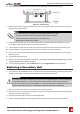
1. ConnecttheDC,asfollows,seeFigure46:
l ConnecttheredwiretoanyoftheDC+terminalsintheinverter.
l ConnecttheblackwiretoanyoftheDC-terminalsintheinverter.
2. Connectthecommunicationwiretothecommunicationboard.
3.
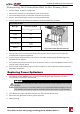
ConnecttheACwiresaccordingtothelabelsontheACterminalblocks,asfollows:
Three Phase Inverter
Wire type Connect to terminal
Figure 48: Primary Unit AC terminals
Line 1 L1
Line 2 L2
Line 3 L3
PE (grounding)
Neutral N
4. Tightenthescrewsofeachterminalwithatorqueof0.88-1.1lb.*ft/1.2-1.5N*m.
5. VerifythattherearenounconnectedwiresattheoutputoftheConnectionUnitandthatany
unusedterminalscrewsaretightened.
6. ConnecttheDCandACwirestotheConnectionUnit.RefertoConnectingtheACandStringstothe
ConnectionUnitonpage32.
7. IfyoureplaceaConnectionUnitwithabuilt-inelectricitymeter,connecttheRS485connectortothe
invertercommunicationboard.
8. Ensureproperconduitsealing;inspecttheentireconduitrunandusestandardconduitsealantsto
avoidwaterpenetration.
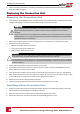
Replacing Power Optimizers
1.
TurnOFFtheinverterON/OFFswitch,andwaituntiltheLCDgreenlightisblinking,orwaitfive
minutesbeforecontinuingtothenextstep.
WARNING!
If a malfunction is indicated by the LEDs, wait five minutes for the input capacitors of the inverter to
discharge.
Si vous ne pouvez pas voir l'écran de l'onduleur ou si un dysfonctionnement est indiqué sur l'écran
LCD, attendez cinq minutes pour que les condensateurs d'entrée de l'onduleur soient déchargés.
2. TurnOFFtheACbreakeranddistributionpanelonthemaindistributionpanel.
3. Disconnectandreplacethenecessarypoweroptimizers.
4. Performpairing
Appendix D: Replacing System Components
Three Phase Inverter with synergy technology Guide MAN-01-00401-1.1
82