
Installation Manual

5.
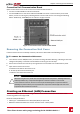
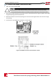
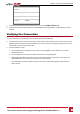
LoosenthescrewsofpinsA(+),B(-),andGineitherthe'Out'or'In'RS485terminalblock.
Figure 37: RS485 terminal block wire connections
6. InsertthewireendsintotheG, AandBpinsshownabove.Useoneterminalblockfortheprevious
inverterinthebusandtheotherterminalblockforthenextinverterinthebus,asshowninFigure38.
YoucanuseanycolorwireforeachoftheA,BandGconnections,aslongasthesamecolorwireis
usedforallApins,thesamecolorforallBpinsandthesamecolorforallGpins.
7.
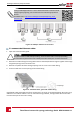
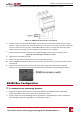
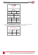
ConnectallB,AandGpinsinallinverters.Thefollowingfigureshowsthisconnectionschema:
Figure 38: Connecting the inverters on a bus
8. Tightentheterminalblocksscrews.
9. Checkthatthewiresarefullyinsertedandcannotbepulledouteasily.
10.
PushtheRS485terminalblocksfirmlyallthewayintotheconnectorsonthecommunicationboard,
seeFigure36.
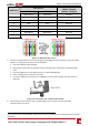
11. TerminatethefirstandlastinvertersonthebusbymovingtheterminationswitchtoON(left
position).TheotherinvertersonthebusshouldhavetheterminationswitchOFF(rightposition).
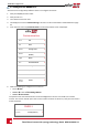
RS485 Bus Configuration
To connect to the monitoring platform:
1. DesignateasingleinverterastheconnectionpointbetweentheRS485busandtheSolarEdge
monitoringplatform.Thisinverterwillserveasthemasterinverter.
2. ConnectthemastertotheSolarEdgemonitoringplatformviatheLANoption(refertoCreatingan
Ethernet(LAN)Connectiononpage60)oranyoftheotheroptions.
Chapter 6: Setting Up Communication
Three Phase Inverter with synergy technology Guide MAN-01-00401-1.1
66